The Glasair III emergency gear extension system was developed to provide gear extension redundancy for complete peace of mind. It separates the emergency extension hydraulic system from the primary gear actuation system for true redundancy. This is accomplished by using separate, single direction hydraulic actuators operated by a hand pump. The emergency system also has a separate reserve supply of hydraulic fluid in case the electric hydraulic pump depletes its normal supply.
For the main gear, the Glasair III down-locks with the heavy duty side brace assemblies must also be installed.
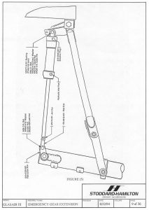
Small ram actuators mounted through the side brace bellcrank brackets and the C-l ribs drive against the down-lock bellcrank brackets to unlock the up-lock hooks, drive the gear down, and lock the gear in the down position. Since the emergency actuators work in only the down direction, just one hydraulic line is needed for each emergency actuator.
The nose gear emergency actuator is mounted on the left side of the nose strut in a similar manner as the primary actuator on the right side. To accommodate the emergency actuator on early Glasair III kits, a second actuator arm must be welded to the nose gear strut.
(Current production Glasair III nose struts have the emergency actuator arm already welded in place.) Although the nose gear emergency actuator resembles the nose gear primary actuator, it is a single direction actuator like the main gear emergency actuators, with fluid only on the forward side of the piston to drive the gear down during an emergency gear extension. A breather is used in the aft end of the actuator to allow air to flow in and out. Unlike the main gear emergency actuators, the nose gear emergency actuator rides< along with the primary system during normal gear actuation.
The landing gear electrical system consists of two independent systems: the gear actuation and the gear position indicator system. The gear actuation system is not affected by the gear position indicator system and, therefore, is less prone to failure modes caused by faulty microswitches or wiring. There are two microswitches per gear assembly in the gear position indicator system; one switch actuates when the gear reaches the down and locked position and one actuates in the up and locked position. The indicator lights for each gear strut operate independently of the lights for the other struts. During the gear extension sequence, a red light comes on first, indicating that the gear strut has been released from its up-lock and is in transit. Next the green light illuminates and the red in-transit light extinguishes to indicate the gear strut is in the down and locked position.
The electric hydraulic pump that provides hydraulic pressure to the landing gear primary actuators is activated by the cockpit-mounted gear switch through two gear system solenoids (four solenoids for the earlier two wire hydraulic pumps). Hydraulic pressure switches automatically shut off the pump when the pressure rises to about 1400 to 1500 psi during gear retraction and about 750 to 850 psi during gear extension. The electric hydraulic pump has internal bypass valves for backup, which are set at least 100 psi higher than the pressure switches (normally about 1000 psi on the gear extension side and about 1750 psi on the gear retraction side, +50 psi).
A panel-mounted override switch is provided in case the gear extension pressure switch fails in such a way that it opens the circuit to the electric hydraulic pump. When actuated, this momentary contact push-button switch completes a circuit that bypasses the gear extension pressure switch, allowing the pilot to run the pump to either extend the gear or to bump up the hydraulic pressure to the pump’s internal bypass pressure. (The hydraulic pump will bypass internally before damage can occur). An amber hydraulic pump indicator light lets the pilot know when the pump is running.
When operating the emergency gear extension system, a selector valve mounted in the center console must be positioned to allow use of the hand pump. The hand pump then pressurizes the emergency actuators to extend and lock the gear.
NOTE: During emergency gear extension, the nose gear up-lock hook is released by a spring that compresses the primary actuator. Before using the hand pump, the pilot must verify that the nose gear up-lock hook has released by watching for the red in-transit light to illuminate.
As the gear is extended with the hand pump, resistance will be felt as each of the main gear up-lock hooks are released and again as the down-locks are engaged. The operator continues to pump the gear down until all three green gear lights come on, indicating that the gear is in the down and locked position.
NOTE: Even in the unlikely event that hydraulic pressure from the hand pump is lost, the nose gear drag brace is held in the extended, over-center locked position by two springs.
NOTE: Hydraulic pressure will not show on the hydraulic pressure gauge during emergency extension because the gauge is only connected to the primary hydraulic system.
The emergency extension selector valve also works as a direct bypass of hydraulic fluid to the reservoir, routing the return fluid around the hydraulic snubber and the electric hydraulic pump’s internal check valve. If the pump runs but fails to extend the gear completely, the pilot may first try to extend the gear by selecting the emergency extension position on the selector valve and allowing the electric hydraulic pump to run the gear down, bypassing any debris or contaminants that might have blocked the normal fluid return passages.
Emergency gear extension procedures
A. Alternative Electric Gear Pump Procedure:
- Slow the aircraft, if necessary, until it is below the maximum gear extension speed (140 mph or 120 knots IAS).
- Select the emergency gear extension position with the emergency extension selector valve. (Turn the handle to the left.)
- Verify that the gear position switch is in the down position. If the gear does not fully extend at this time, proceed to the Emergency Hand Pump Procedure, step 1.
B. Emergency Hand Pump Procedure:
- Pull the main hydraulic pump circuit breaker (40 Amp for a 12 volt system with a three-wire pump; 25 Amp for a 24 volt system with a three-wire pump or for a 12 Volt system with a two-wire pump).
- Press the push-to-test button to verify that all the gear position indicator lights illuminate.
- With the selector valve still in the emergency extension position and the gear position lever in the down position, verify that the nose gear up-lock hook has released, indicated by a nose gear in-transit red light.
- Proceed to pump the gear down with the hand pump. This will release both main gear up-locks, extend all three gear struts, and lock them in the down position. Verify that all three gear struts are down and locked as indicated by the three green lights.
All new Glasair III kits sold have the new Emergency Gear Extension system included. For early Glasair IIIs delivered with out the new Emergency Gear Extension system, use stock # 353-5800-502 to place your order.
Note: As mentioned above the Glasair III down-locks with the heavy duty side brace assemblies must be installed to adapt the new Emergency Gear Extension system.
Reference the G-III Side Brace-Down Lock Assemblies: stock # 353-5205-103 (left side), and #353-5205-104 (right side).


