Specifications:
- 2-5/8″ increase in prop clearance.
- Approximately 5 lb weight gain with larger wheel, tire and tube.
- Approximately 1 lb weight increase with extended forks.
Parts you will need: (in addition to 5.00 x 5 wheel, tire and tube)
- 362-5932-001 Axle, Nose Wheel (1) *
- 361-5912-002 Hub, Nose Wheel Axle (2)*
- 361-5912-002 Laminated washer (1) *
- AN4-56 bolt, drilled shank (5-5/16″ grip length) (1) Aircraft Spruce
- AN960-416 washer (3)*
- AN310-4 castle nut (1)*
- AN 380-2-2 cotter pin (1) *
- 3/16″ dia x 1/4” length roll pin (4) (hardware store)
- NAS73-4-014 bushing (1)*
*Source: Glasair Aviation
Start by tracing out the existing fork and axle bolt hole on a piece of thin cardboard. Mark the bend line. Then draw a new hole location 1.15″ aft and 1.25″ down as shown:
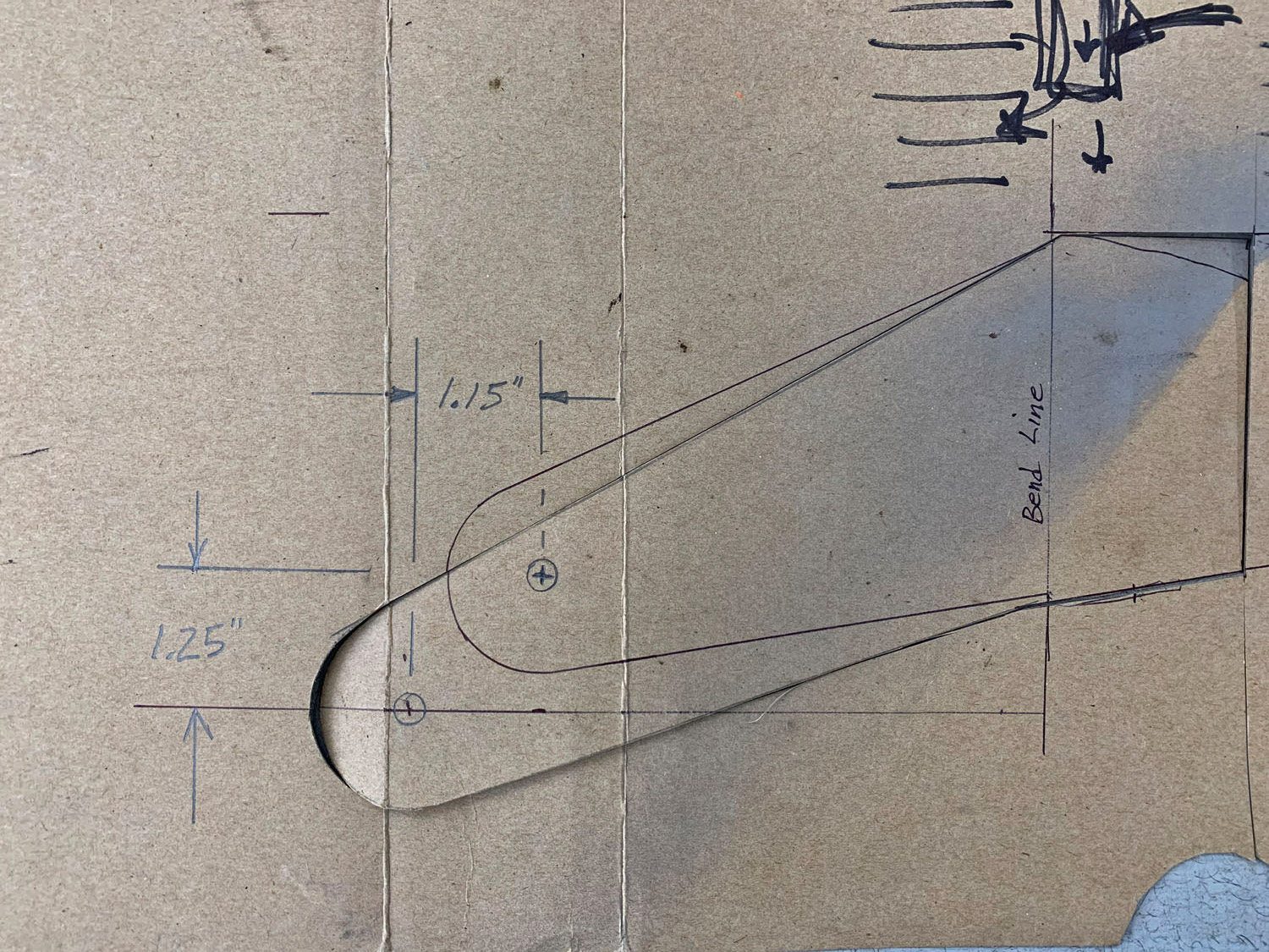
Draw the same radius as on the existing fork and extend the lines back to the main body. Extend the new fork 2.0″ forward of the bend line. Cut the new fork shape from the cardboard and make two tracings onto a piece of 4130 steel plate.
Cut the new forks out of the steel plate. I used a 4.5″ angle grinder with a thin cut-off wheel. Sand and deburr all edges smooth.
Bend the new forks along the bend line 27°. Be sure to bend opposites!
Center punch and drill the 1/4″ axle holes in the forks. Start with a small drill and work up to the final size. If you have a 1/4” reamer, drill the final hole to 7/32″ and ream to .250″.
If you mess up, you can always drill and ream up to 5/16″ size and install a NAS77-4-012 hat bushing (like I did because I assumed the axle bolt was 5/16″ diameter before I consulted the assembly manual!) Use red Loctite when you press the bushing in. Then stake the bushing with a center punch.
 Press two 3/16″ x 1/4″ length roll pins into the end of the axle to prevent rotation in the hubs.
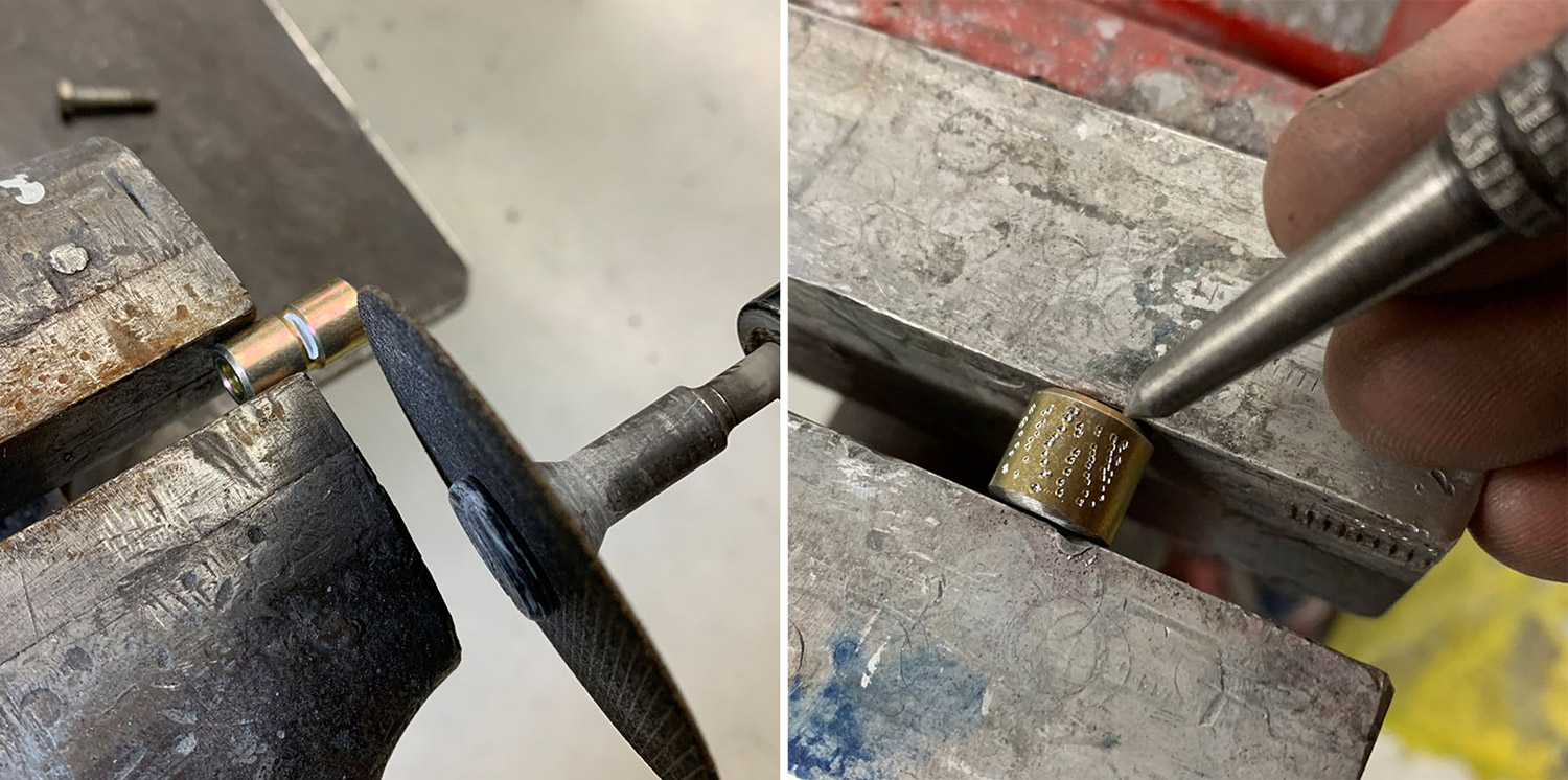
Cut the NAS73-4-014 bushing in half and deburr the ends. The bushing was not a press fit, so use a sharp center punch with light taps with a hammer to “knurl” the surface of the bushing to enlarge it enough for a press fit. Press them in place on the axle hubs with Loctite red.
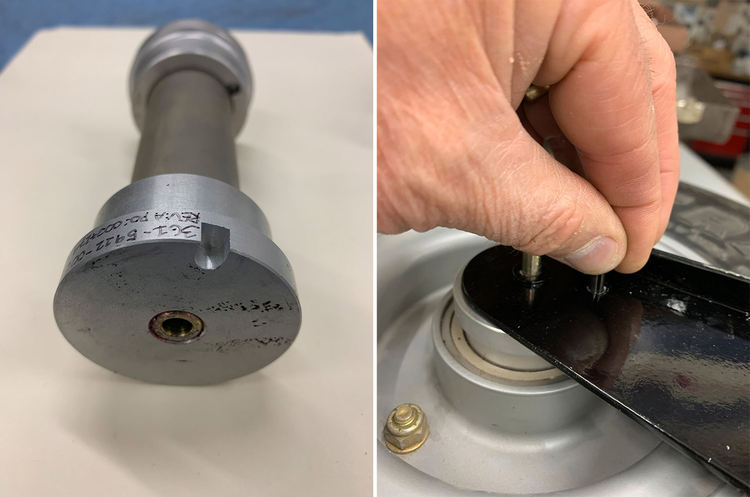
Press the bushings into the hubs. Place the axle hubs against the new forks with the bolt in place and scribe the outline of the small notches onto the fork. Center punch the forks and drill up to 3/16″ diameter. Install a 3/16″ diameter roll pin x 1/4″ length in each fork.
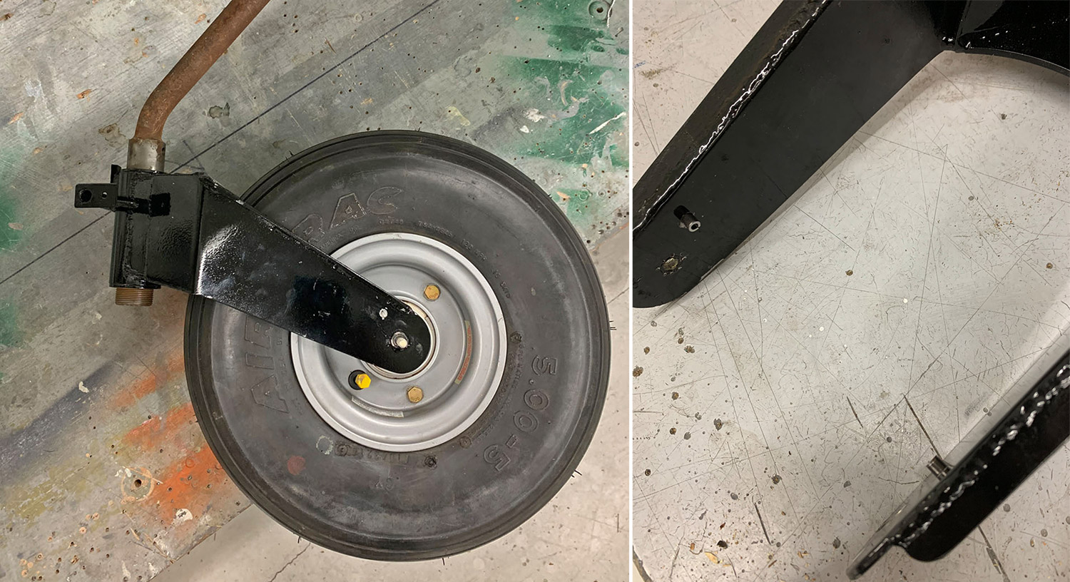
Assemble the axle and axle hubs onto the nose wheel and tire.
Cut the existing forks from the nose fork assembly at the outboard edge of the bend. (there’s no turning back now!)
Roughly fit the new forks to determine where to remove paint from the fork body. You will want to have clean steel to obtain quality TIG welds.
Install the new forks on the hubs with the AN4-56 bolt, washers and AN310-4 castle nut
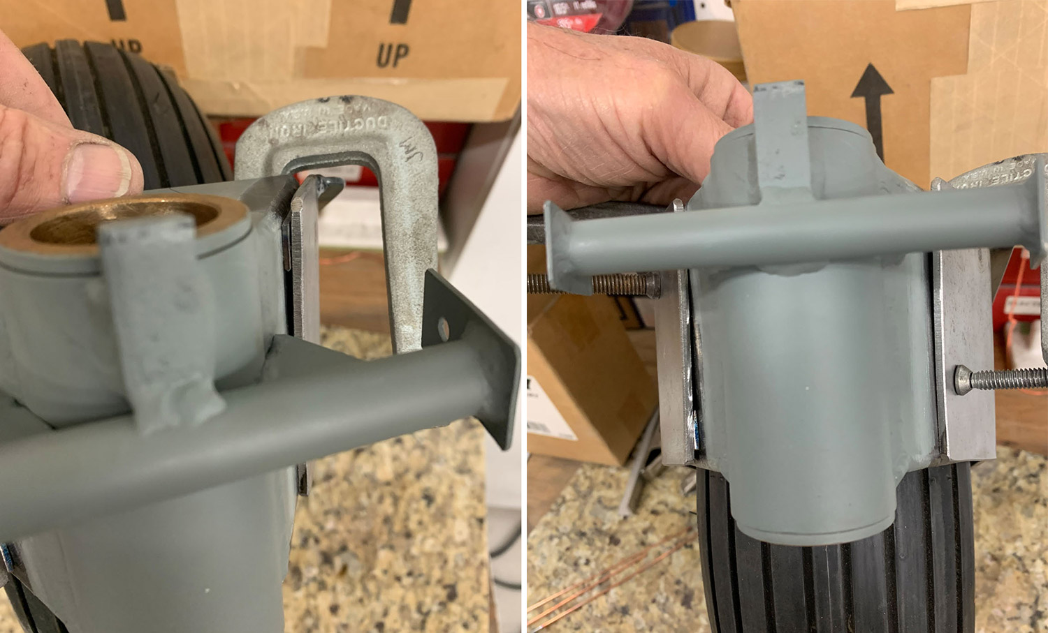
Look closely and see the thin piece of 4130 steel shim I installed between the fork and the body. I discovered this was necessary to achieve the requirement of keeping the wheel and tire vertical to the nose gear axle. The final shim thickness ended up being approximately 1/32″ thick (half of what is shown above).
Tack weld the new forks to the body before removing the tire and wheel. Or bring it to your local TIG welding buddy with a fresh box of donuts.
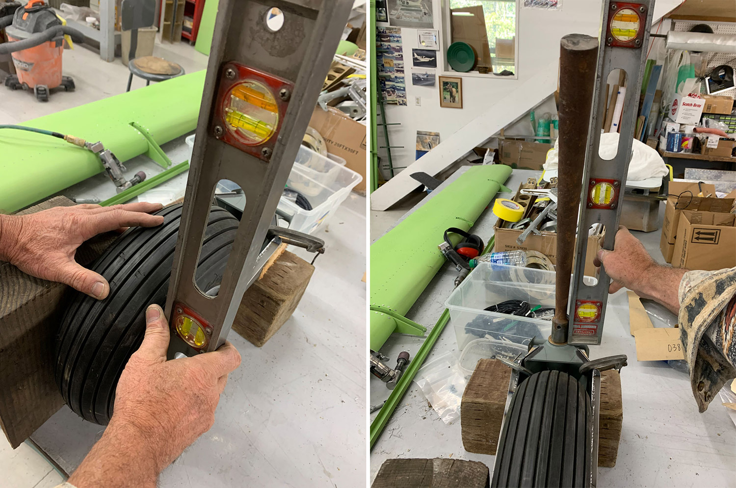
Set the tire and nose gear axle vertical.
 Because the forks are getting longer than originally designed, I felt it was prudent to weld a 1/2″ wide stiffener to the top edge of the forks facing outboard.

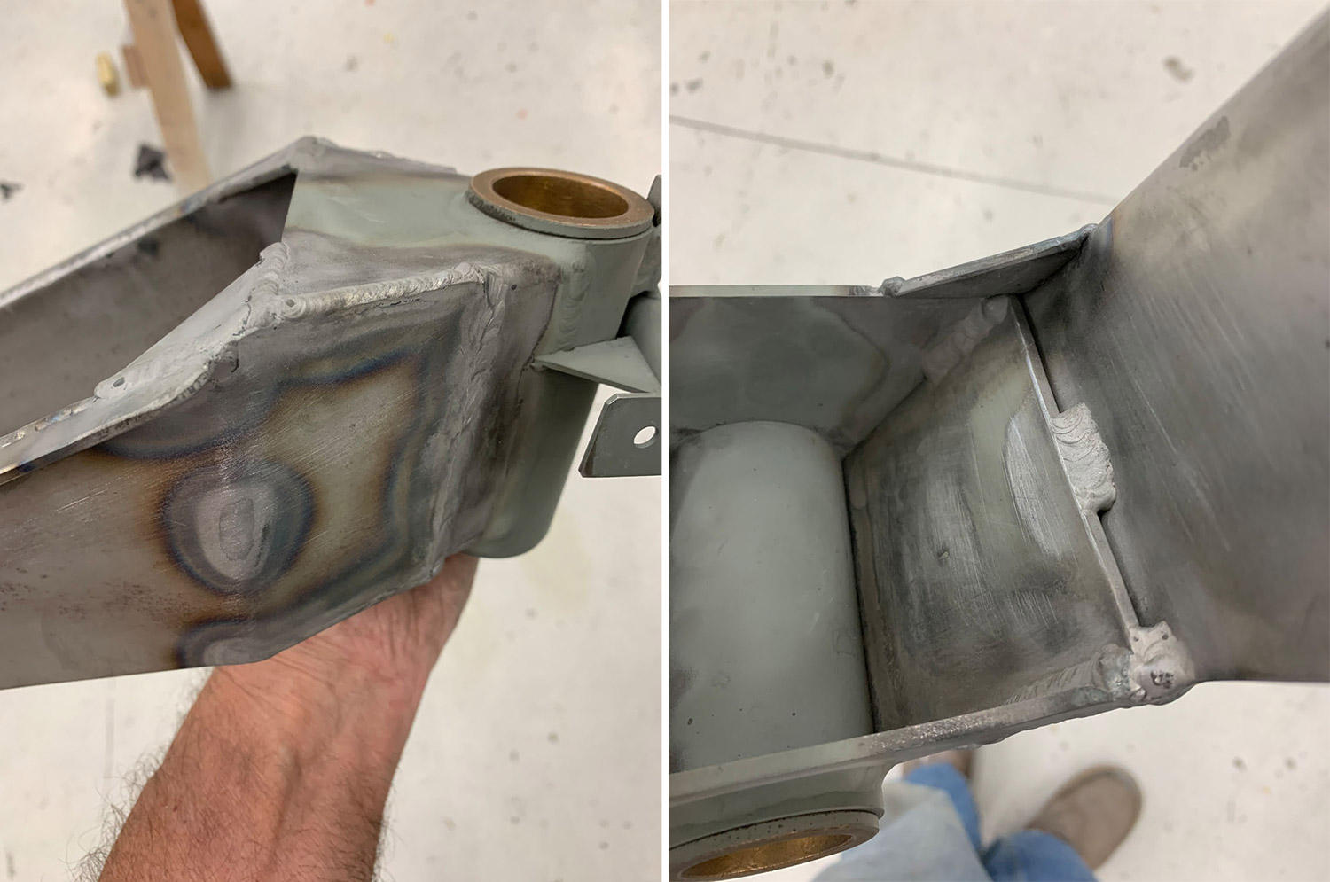
Once the tack welds are holding the forks from migrating, complete the external welds between the fork and body. Then weld an internal bead approximately 3/4″ long internally in the middle of the fork as shown. To avoid a stress line, DO NOT weld the internal seam other that the portion shown in the middle.
Finally, cut two corner gussets on the top of the fork and weld in place.
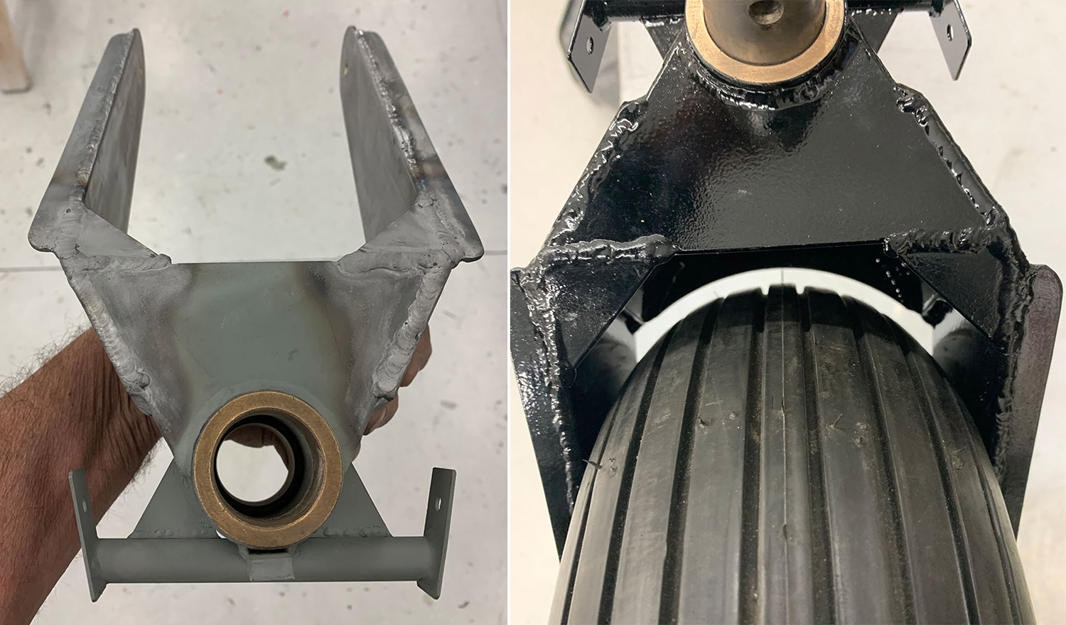
Once all welding is complete, I sand blasted the whole assembly to prepare it for primer and paint. To avoid internal corrosion, seal the non-welded portions of this seam with caulking such as Silpruf or any off the shelf silicone caulk after painting.
Here’s the finished fork assembly. Don’t forget to check for bearing play and install the necessary axle shim material as described in the GlaStar assembly manual.
Upsizing the wheel and tire to 5×5 size gives 1-3/8″ more prop clearance. Extending the fork down 1-1/4″ gives a total gain of 2-5/8″ prop clearance.
The weight difference of the larger tire and wheel is approximately five pounds. I neglected to weigh the original fork. The new fork is estimated to be one pound heavier.


