 This article is long overdue! What’s here is a condensed version of a long forum topic I started entitled, “VGs on a Sportsman.” Like many of you, I bought my Sportsman because of its versatility…a four-seater that was capable enough to operate in the back-country, but fast enough to go cross-country. Adding vortex generators (VGs) on top of the wing is a common modification for many backcountry planes. They lower stall speed which allows for slower approach speeds and hence shorter landings, and they add controllability at high angles of attack or even in a stall… so says the orthodoxy. Yet, their performance on a Sportsman (or GlaStar) has mixed reviews by people in this forum. Some say they do exactly what they promise, and others say they don’t do anything on a Sportsman/GlaStar.
In May-July 2020, I flew a series of tests using three types of vortex generators in various configurations on my Sportsman, Miss Juliet. My goal back then was to lower my plane’s flaps-down stall speed without slowing her down in cruise. I’ll save some of you the pain of reading my prose and tell you this now:
I was unable to significantly reduce my Sportsman’s flaps-down stall speed using VGs, but they did lower flaps-up stall speed
I know many of you are fans of VGs because of controllability gains…both more elevator authority when installed under the horizontal stab, and tamed/mushy stall characteristics. Neither of these were objectives of mine back in 2020. Still, I did test under the stab VGs, and stall characteristics where inherently tested by flying so many stalls. I’m sad to report no noticeable gain in elevator authority or stall characteristics in any of my tests. Thus, I won’t discuss these aspects further.
For reasons I will explain at the end, I have renewed interest in VGs now (2024) because they lower flaps-up stall speed. For now, let’s return to what I did in 2020. Do VG’s on a Sportsman lower its flaps-down stall speed?
Theory
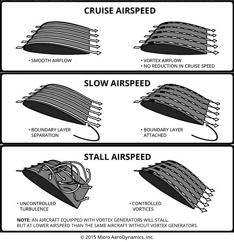
Vortex generators (VGs) are small wing-like fins that redirect an airflow into a vortex. When mounted properly on top of a wing, vortex generators can lower the stall speed of an aircraft. They accomplish this by re-energizing the flow over the wing such that it delays flow separation from the wing at a higher angles of attack than what would occur without the vortex generators.
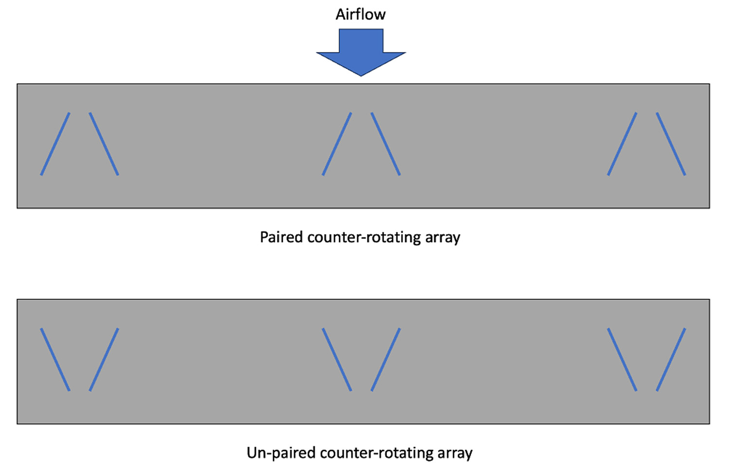
To do this effectively, they should be angled against the incoming airflow inducing a vortex, mounted along the majority/entirety of the wing’s span, and located behind the leading edge far enough back to prevent flow separation, but close enough to the leading edge so they extend beyond the boundary layer and into the high-speed airflow. On straight wings, VGs should be mounted in counter-rotating arrays. On delta-winged planes, VGs should be mounted in co-rotating arrays.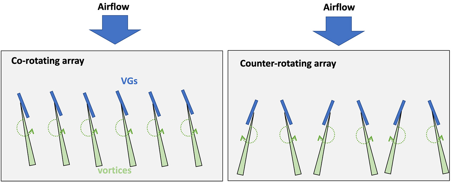
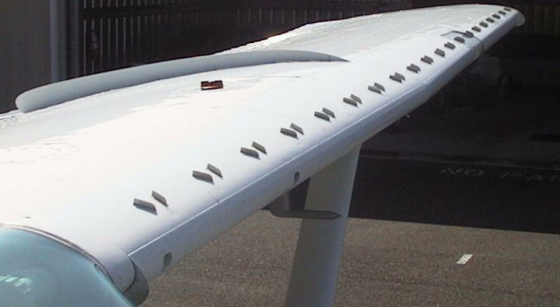
Note—The Sportsman and GlaStar each employ four large delta-winged VGs mounted parallel to the wing on small pylons. These VGs are designed to energize the flow going over the elevator/rudder (inboard VGs) and ailerons (outboard VGs) to improved high AoA maneuverability. Each VG produces two counter-rotating paired vortices at high AoA.
The book “General Aviation Aircraft Design: Applied Methods and Procedures” by Snorri Gudmundsson has the following VG placement guidance:
- Height: 1 to 2 times the boundary layer thickness at their position
- Aspect ratio: 0.25 to 1.00 (AR = height/ chord)
- Taper ratio: 0.6 to 0.8 (recommended to help “load up” the VG and make it more effective)
- Angle-of-incidence: 10° to 20°
- Spacing: 5 to 10 times the height
- Chordwise location: approximately 20 boundary layer thicknesses ahead of the separation point
- Orientation: for unswept wing use counter-rotating VGs (possibly even in pairs). For swept wings use co-rotating VGs.
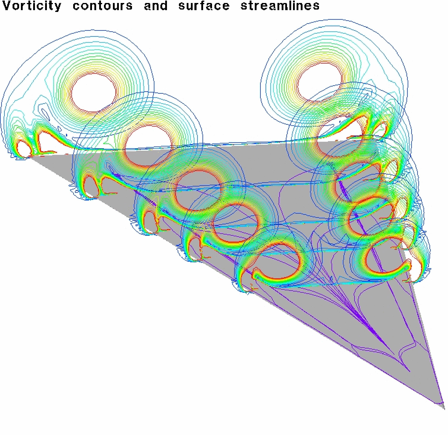
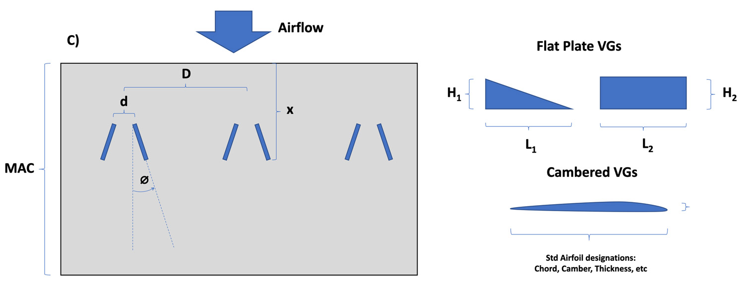
Aerodynamically, delta-shaped VGs should produce better vortices than rectangular ones.[1]
Guidance and Common Practice
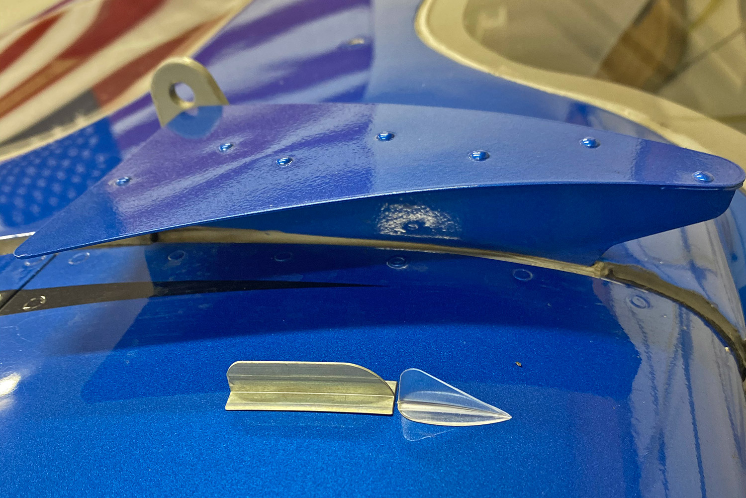
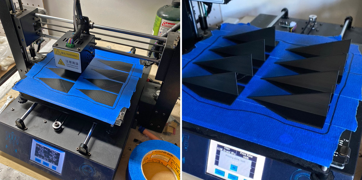
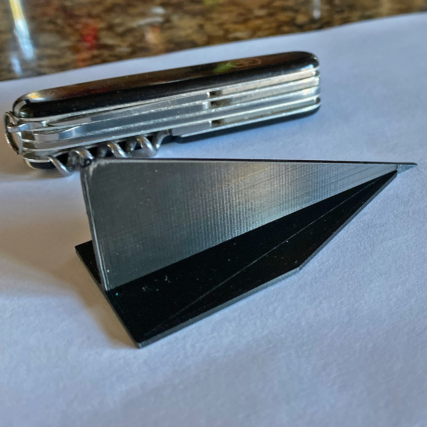
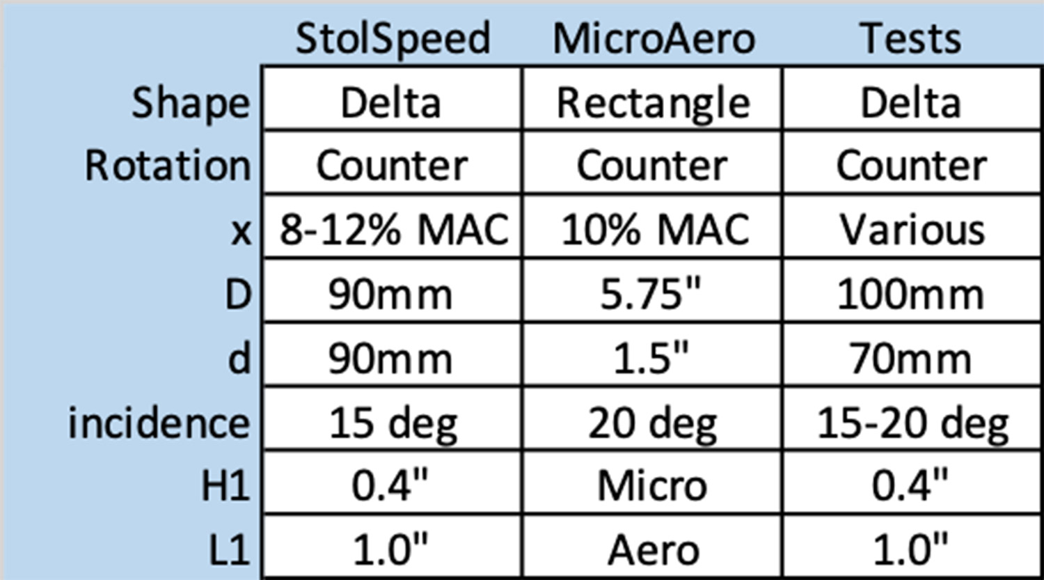
I tested three VG types on my Sportsman. Delta-wing STOLSPEED VG’s (https://stolspeed.com), rectangular Micro Aerodynamics VGs (https://microaero.com), and home-made 3D-printed delta-wing VGs.
Back in 2020, STOLSPEED recommended placing their VGs at 8-12% of the wing’s chord (MAC—mean aerodynamic chord) behind the leading edge, in counter-rotating pairs angled 15 degrees against the airflow. They have since changed that recommendation to 5% MAC, interesting.
Also in 2020, Micro Dynamics recommended placing their VGs at 10% MAC, in counter-rotating pairs angled 20 degrees against the airflow.
Looking at pictures of VGs mounted on various high-wing planes, common-practice seems to place VGs at 10% or less of MAC.
Tested Configurations and Results
I experimented with placing VGs rows at 5%, 8.4%, 9.5%, 10%, 28.8%, and 32% MAC, using three types of VGs, two incidence angles (15 and 20 degrees), paired counter-rotating, unpaired counter-rotating arrays, and did some experimentation with co-rotating VG arrays.
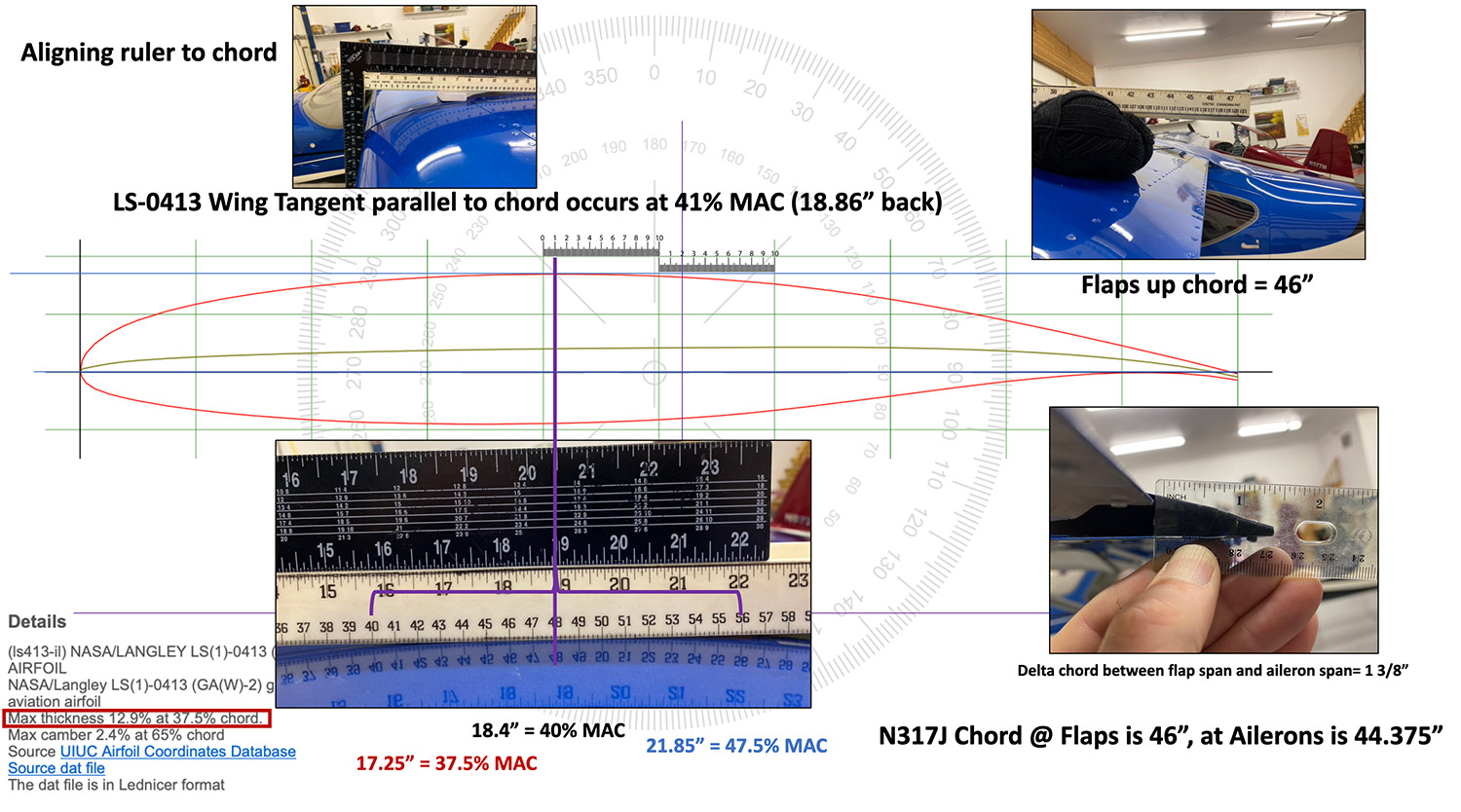
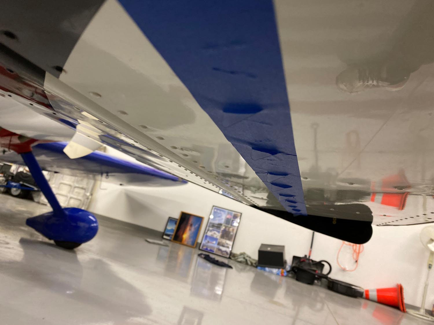
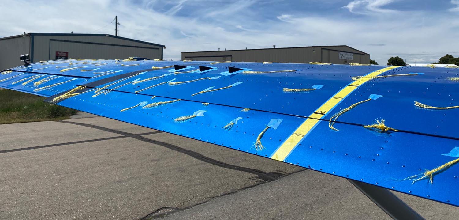
Finding the %MAC on the wing is not nearly as simple as putting a tape measure on the wing and pulling it back to your desired point because the wing is curved. %MAC is measured on a straight line from the leading edge to the trailing edge. My solution was to compute the tangent point on the airfoil, then do my best to align a long ruler (level) to hit the same tangent point.
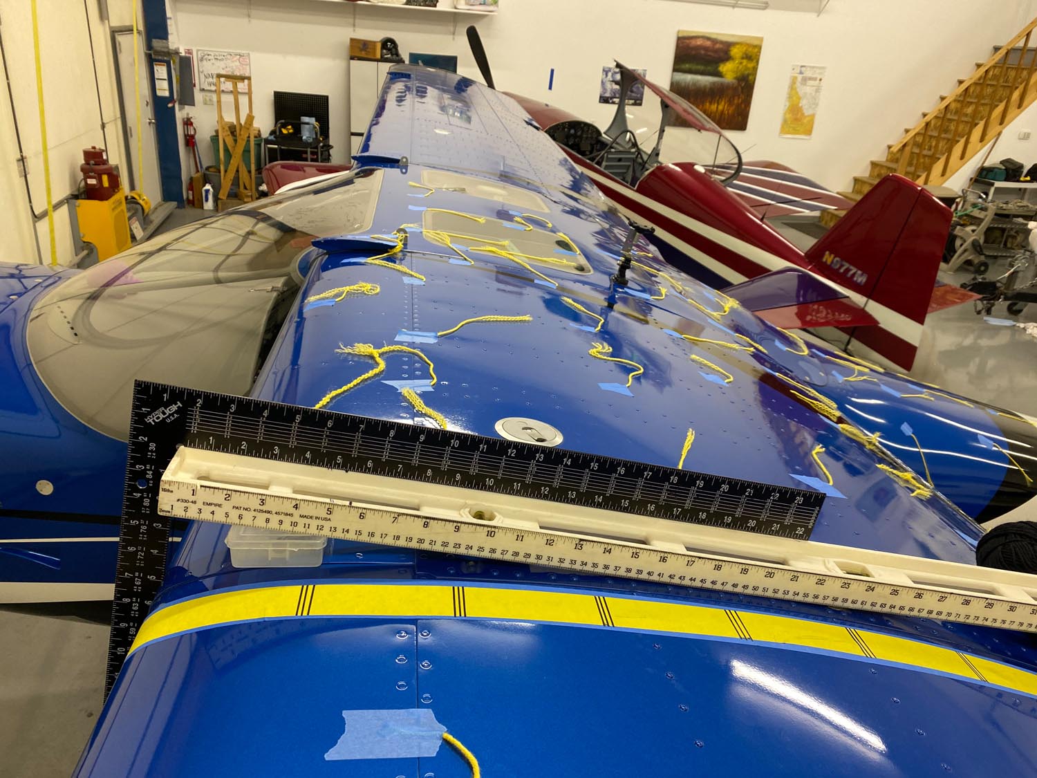
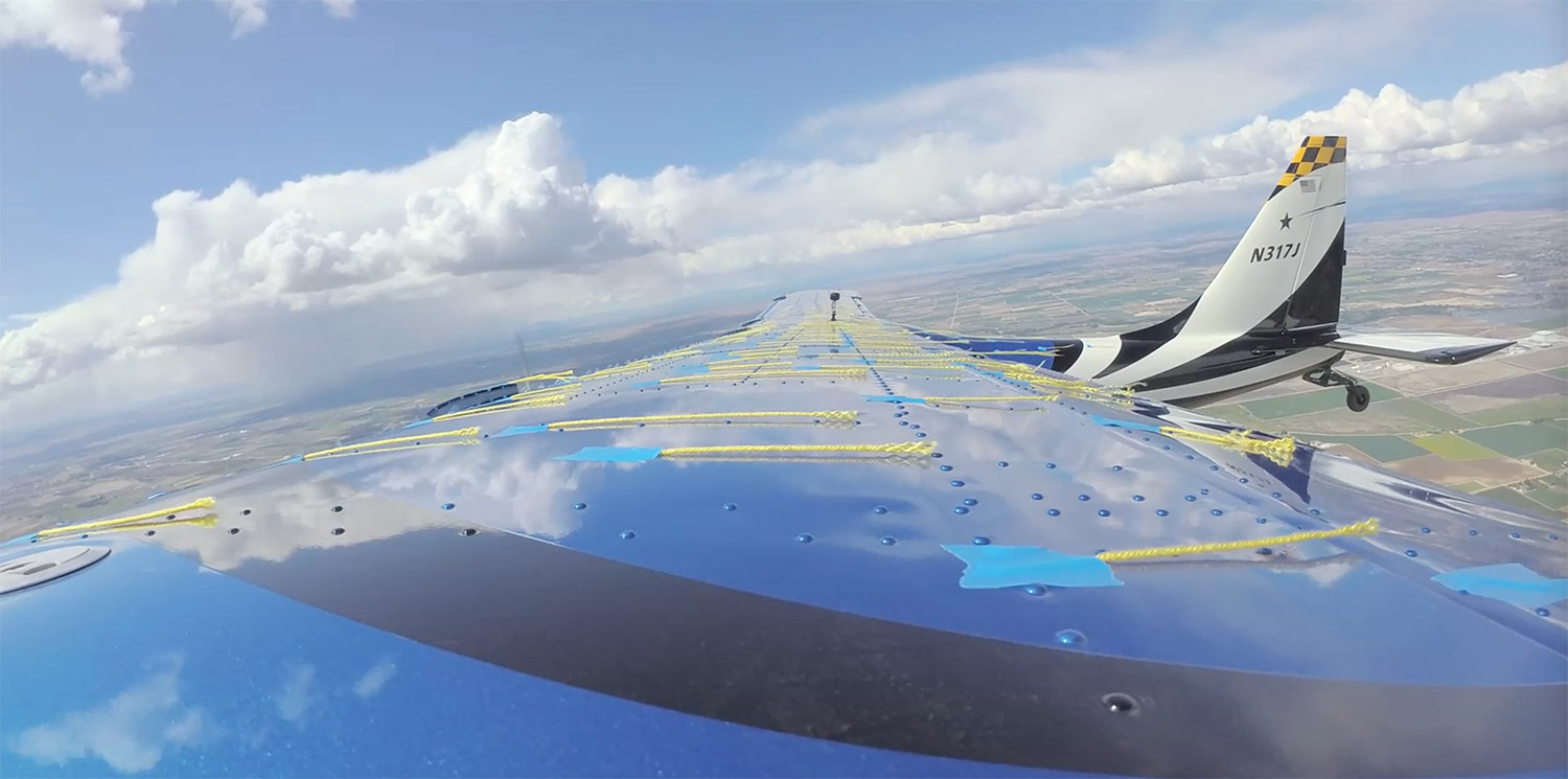
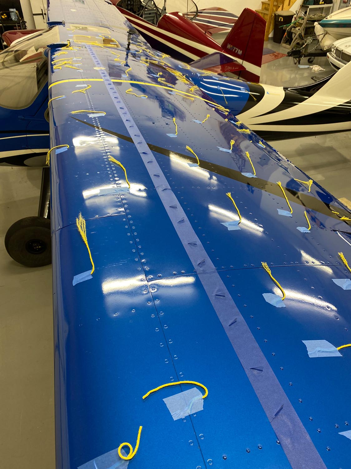
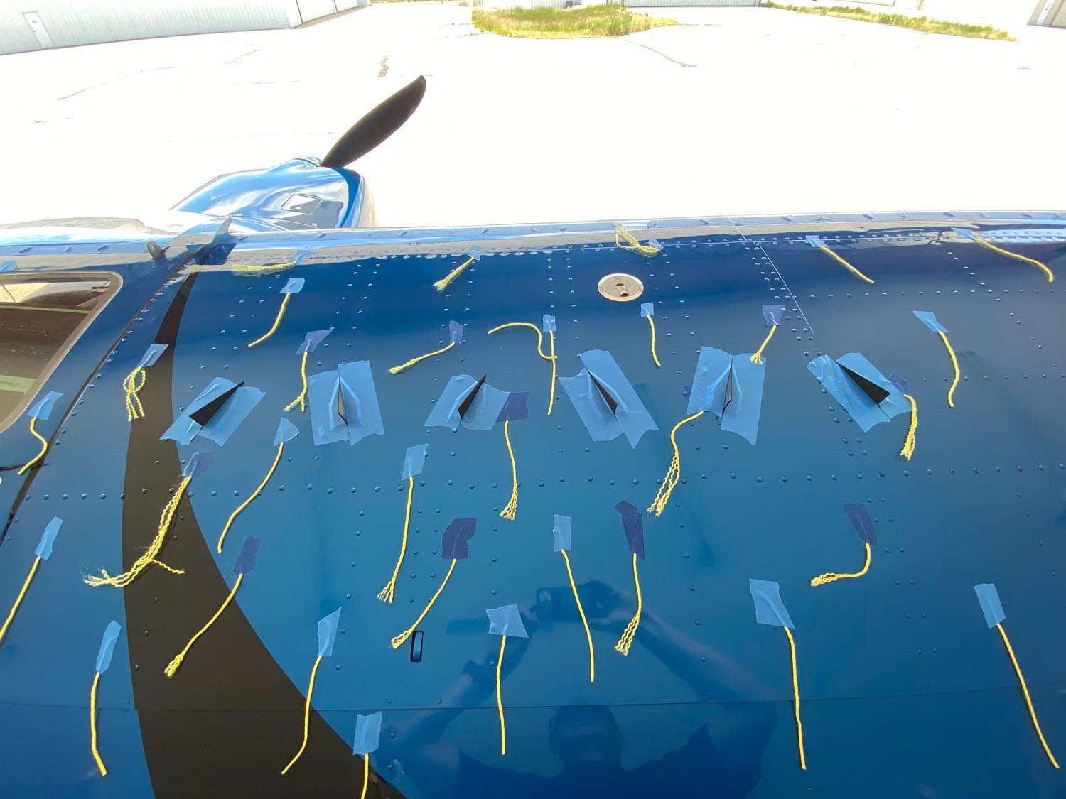
After setting up my MAC reference ruler, I added a yellow reference strip marked every 10% of MAC and added several more tufts, mostly to the right wing so both wings now had tufts.
Determination of Stall Speed
My Sportsman is not instrumented like a testbed would be by a manufacturer testing their prototypes. I fused cockpit and tufted-wing video, G3X recorded data, and my own eyes to determine the stall speed for each test stall. I estimate this technique was accurate to within about 1-2 knots indicated airspeed.
Here’s why.
Garmin G3X outputs data every second to an SD card. The video cameras capture at 30 frames/second. A lot happens in one second during a stall. On the video side, I’d say that 30 fps is sufficient to “call the stall.” The trouble becomes correlating a time-stamp on the video with what the G3X records with what the pilot saw. Not always, but in many cases, the indicated airspeed recorded by the G3X changed by up to 2 knots from one second to the next during the stall. And several times the video would show a stall occurring midway between seconds. Which G3X measurement then is primary, the one before the “video” stall or the one after? Or average them? For that matter, does the G3X stamp data exactly on the second, or somewhere in between, and how far de-synched are the G3X and the video camera timestamps?
Two other issues also hamper determination of stall speed. The first is pilot technique. Stall entries are more accurate if the aircraft is slowing down not more than 1 knot per second. Higher deceleration rates can produce erroneous recorded stall speeds. The second issue is the pitot-static system. At high angles of attack, the pitot-static system becomes increasingly less reliable. The “good” news is we are after relative differences in stall speed, not the actual calibrated stall speed of the plane. Presumably, this means we are still doing an “apples to apples” comparison, even if the actual speed is wrong.
Test Flights
The takeoff gross weight was 1950 lb for each test flight and stalls were flown in the same order and general area (meaning distance from takeoff to practice area was the same for each flight).
3D Printed Big VGs
Given the limited number (9) of printed Big VGs, the approach was not to see if they lowered the stall speed, but, using tufts on the wing behind them to see if they could keep the flow attached longer than the rest of the wing without them. They did not. In fact, each big VG case had a higher stall speed than its identical non-Big VG case…maybe the big VGs were more like spoilers!
Results
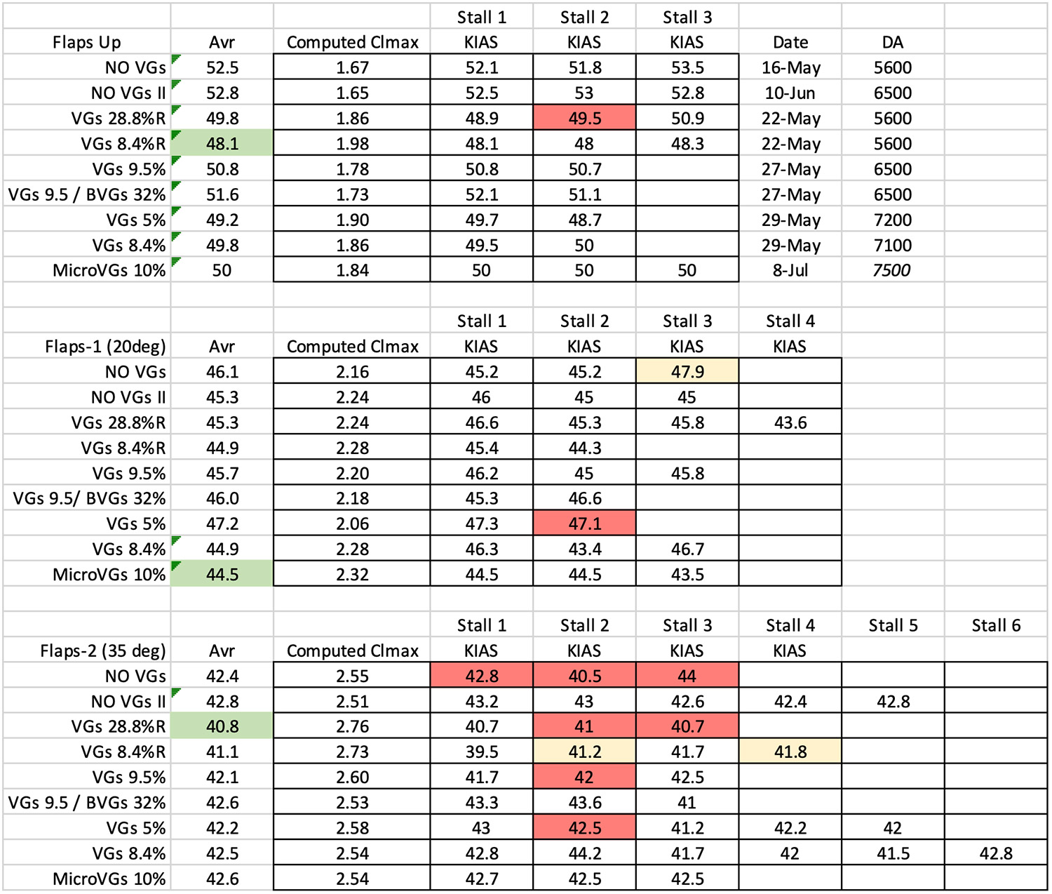
Legend
VG = StolSpeed VGs, BVG = 3D Printed Large VGs, MicroVG = Micro Aerodynamics VGs.
No VGs II = second set of baseline stalls
“R” – unpaired counter-rotating array. Lack of “R” = paired counter-rotating array.
GREEN = best configuration; RED = stall interpolation issue; YELLOW = poor pilot technique.
The best configuration flaps up came from STOLSPEED VGs at 8.4% MAC arranged in an unpaired counter-rotating array. It reduced stall speed from 52.65 to 48.1 KIAS (-4.55 knots).
The best configuration flaps 1 (20) came from Micro Aerodynamics VGs at 10% MAC arranged in a paired counter-rotating array. It reduced stall speed from 45.7 to 44.5 KIAS (-1.2 knots).
The best configuration flaps 2 (35) came from STOLSPEED VGs at 28.8% MAC arranged in an unpaired counter-rotating array. It reduced stall speed from 42.6 to 40.8 KIAS (-1.8 knots).
Points to Ponder
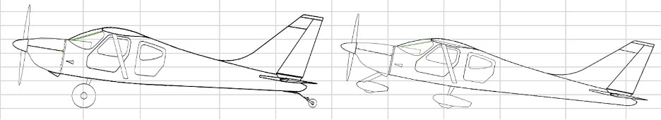
On a taildragger, if your pitch angle in the flare exceeds your plane’s 3-point parked pitch angle, you will land tail-first. If you don’t want to do that, the 3-point pitch plus or minus the wing incidence angle yields the maximum angle of attack that you plan to land with…this angle (~8-10 degrees) is below the Sportsman’s unmodified stall angle of attack (13.4 degrees flaps full).[2] So, the “game” is not actually to lower stall speed, but generating more lift at your 3-point sitting angle of attack. The good news is that VG’s should move the wing’s coefficient of lift curve both right (delay stall) and up (lift profit). And because they raise the curve up, there is an added benefit of a shorter takeoff, too.
The figure below is from a study which evaluated the use of VG’s on a NACA 4412 airfoil, which is NOT the foil on the Sportsman or GlaStar, but it is illustrative.[3] “Controlled” flow is the airfoil with VGs, and “uncontrolled” is the clean airfoil w/o VGs. What we see is the CL gain at 3-point AoA (10 deg) is less than the maximum gain which occurs at stall (17-19 deg). The CL “lift profit” increases as AoA increases up to stall.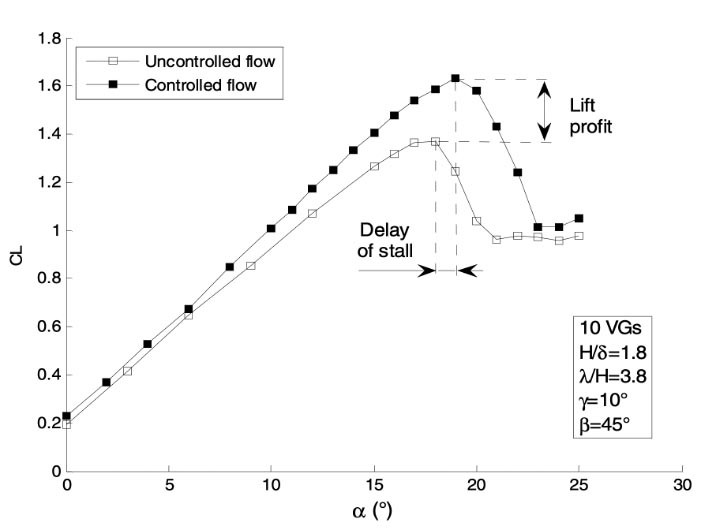 On a Sportsman trike, the maximum pitch angle before dragging the tail is about 11 degrees, which is about 12 degrees of AoA. Thus, a trike theoretically has more to gain from using VGs, at least for an unmodified Sportsman.
 On % MAC placement. While the 28.8% MAC placement performed the best, aft VG placement (>15%) on a Sportsman wing suffers two practical drawbacks. First, the gas caps are at 25-30% MAC, and you don’t want to spill fuel on STOLSPEED VGs since they will deteriorate according to the manufacturer. Second, the base of each VG is curved. Past about 15% MAC, the wing gets nearly flat and the VGs won’t conform requiring work arounds with respect to permanent attachment.
On hassle factor. Besides the time spent installing VGs, they also make it more difficult to clean the wing and may/will likely fall off at some point requiring continued maintenance.
On cruise speed. VGs create more drag. While I never reached the cruise flight test stage in my flight tests (because they didn’t prove out in the landing phase in my mind), they must have some penalty in cruise despite the claims of the manufactures which say you don’t lose in cruise. It might be so small as to be negligible…or not? On this point, the larger delta winged VGs on the tops of our Sportsman and GlaStar wings are intriguing because they are mounted streamlined into the airflow in cruise (minimal drag). As AoA increases, they start to “bite” and create vortices. This of course increases drag, but, they are “ideal” in that they minimize drag in cruise and only create significant vortices when you need them, as opposed to Micro or StolSpeed VGs which create vortices (and drag) at all speeds and AoAs.
Conclusion
When practical placement considerations are taken into account (see points to ponder), the best tested VG/placement to reduce flaps-down stall speed on a Sportsman is using an unpaired array of counter rotating StolSpeed VGs placed at 8.4% of MAC. This yielded a stall reduction of -1.5 knots, but this reduction is also within the 1-2 knot error-band in determining the stall speed.
Assuming this reduction is real, what does it mean for landing performance? If you look at the table below showing Sportsman ground rolls for 1700, 2000, and 2350lb planes, you can see a 4-5 knot reduction in approach speed (Flaps-1 versus Flaps-2) translates to 60-80 feet of ground roll reduction on a paved surface and 90-110 foot reduction on grass.[4] That’s if we could reduce approach speed by 4-5 knots. The VG flight test data shows only -1.2 to -1.8 knot stall speed reductions for flaps 1 and flaps 2 respectively, which translates to -1.6 and -2.3 approach knots. The column labeled Grass w/ VGs shows landing rolls resulting from a -2 knot approach speed. My judgement is these performance increases are essentially irrelevant.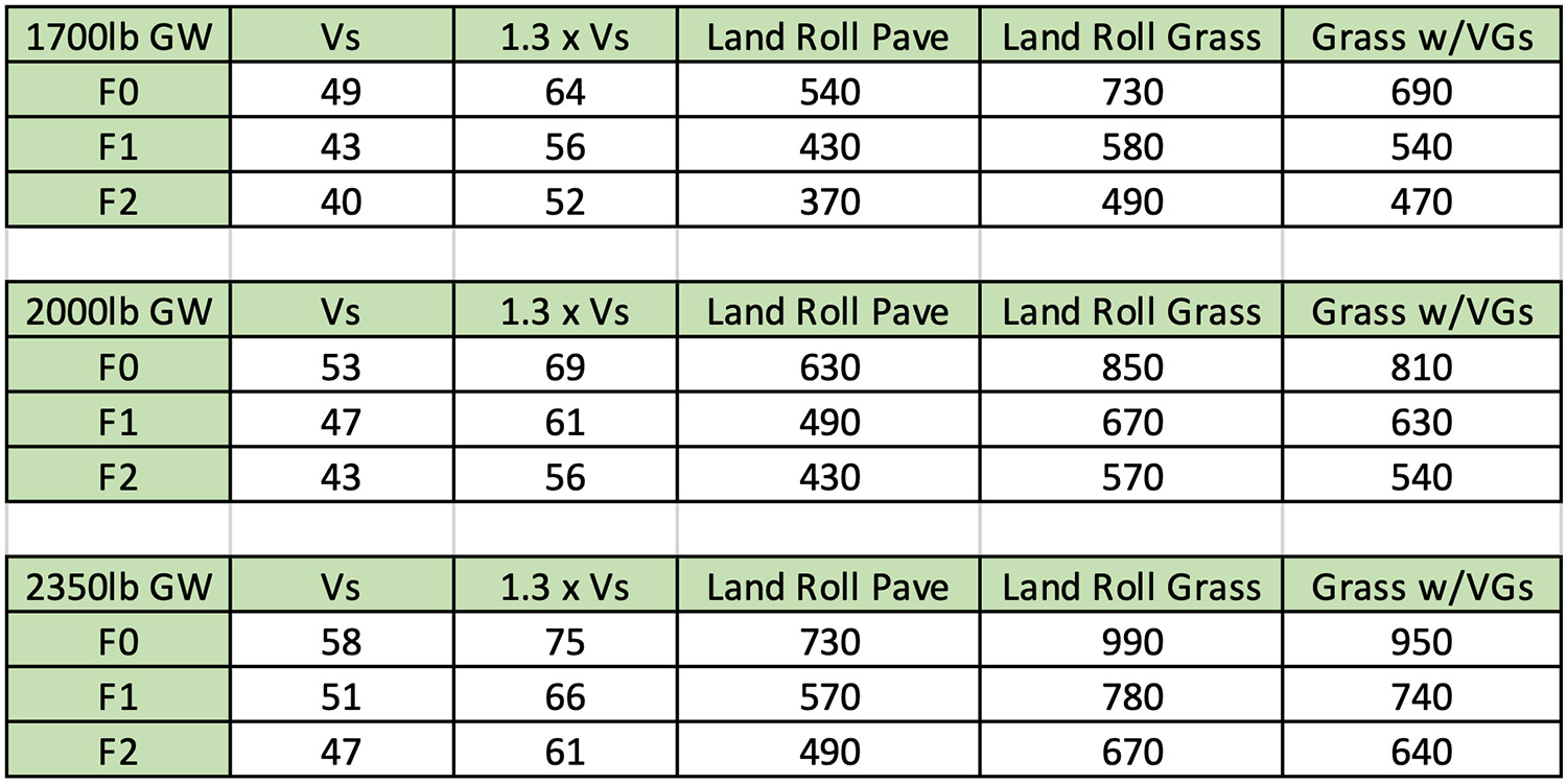
Thus, I conclude that wing-mounted VGs are not worth it on a Sportsman for STOL purposes. Still, if I were to install VGs, I’d test a few more configurations before gluing them on: StolSpeed VGs in paired and unpaired counter-rotating arrays at 5%, 7.5% and 10% MAC, at least one test with co-rotating arrays, probably at the %MAC that tested the best with counter-rotating arrays. Might even experiment with an array of delta-wing VGs on pylons… that’s a lot of work…so… I’m in no hurry.
But Why?
Best guess: the Sportsman flap design creates a large pressure gradient that VGs cannot suppress. The Cessna 172S has a 5 KCAS split between flaps up stall speed and full flaps stall speed. The Sportsman has an 11-knot split, requiring a much greater pressure gradient. When that flow wants to separate, it takes a much stronger vortex to stop it. If so, this might explain why some GlaStar owners see gains with VGs, afterall, the GlaStar POH shows a 6-knot stall split. I’d be curious to know if those same GlaStars have the original flap design, or the latter Sportsman one?
Renewed Interest
Up to this point we’ve summarized the VG stall testing I did back in 2020 with the objective of lowering flaps down stall speed. Last Summer, I exhibited at OshKosh 2023. While there I met a group of aviators and engineers who have been working diligently on the “turn back” problem. This problem is basically about what to do if you lose power shortly after takeoff and when does it become possible to turnback and land opposite direction on the runway you just left. It has consumed a lot of brain cycles since then and could easily be the subject of another article.
It’s striking and sad how many aviators die trying to turnback to a runway after an engine failure on takeoff. The statistics don’t lie:
NTSB data since 1 January 2013 include 133 turnback attempts after partial or full power loss during initial climb. Of those attempts, 9 were successful (7 of those were partial power loss and 2 were to long runways). The exact number of turnbacks that resulted in successful landing and not reported is not known; but based on available mishap data, it is reasonable to estimate the actual number of successful turnbacks is low. Mishaps where the pilot maneuvered ahead of the wing line were 35% fatal. The fatal rate when the pilot attempted to maneuver aft of the wing line nearly doubled to 59%. For turnback attempts below 600’ AGL, 54% stalled with a 95% rate of severe or fatal injury. Aircraft that maneuvered ahead of the wing line, 8% stalled with a 71% rate of severe or fatal injury. The probability of severe or fatal injury because of stall and loss of control following power loss is high when post engine failure maneuvering is attempted. This contrasts with the 25% fatality rate for EAB airplanes that hit structures on the ground (worst-case scenario) under control. Mishap rates are relatively consistent regardless of pilot experience, license, or ratings, including instructors. Fully 1/3 (28-38%) of all pilots attempted turnback, regardless of altitude, and 28% of all attempts were below 200’ AGL.[5]
Which brings me back to the VG question. VG testing from 2020 clearly showed a stall benefit using VGs on the Sportsman when flaps are up (-4.55 knots). The best configuration to execute an emergency turnback is also flaps up to minimize drag and minimize altitude loss in the glide back. Yet, the biggest threat in the turnback maneuver is stall/spin. Seems VGs have a safety benefit that I had not really thought about.
There’s a related issue to think about here too and that is stall calibration on your EFIS. This discussion has hatched a few times in the forum before, usually about how to calibrate, nuisance alarms, etc. I’ve calibrated my G3X to my flaps down stall speed, which is perfect for day to day flying as it gives me great SA on final approaches and STOL approaches without giving me nuisance alarms. However, it also results in late to no stall warning when flaps are up, which means it will/could fail me if and when I need it the most.
The best solution is to calibrate your EFIS for each flap setting you use (if your EFIS can do that). Garmin recently released this capability for the G3X, so I am following those builders/owners who are wiring their G3X to do multiple flap settings. Until then, I’m likely to recalibrate my stall warning for flaps up and hope it doesn’t give me lots of nuisance warnings on approach with flaps down.
Now about those VGs…
References
[1] https://www.sciencedirect.com/topics/engineering/delta-wing
https://royalsocietypublishing.org/doi/10.1098/rsos.170077
https://www.researchgate.net/publication/275383294_Lift_Force_of_Delta_Wings
[2] Modifications such as extended gear and large tires increase the sitting angle and therefore increase the landing angle of attack before landing tail first.
[3] Hocine Tebbiche and Mohammed S. Boutoudj, “Passive Control on the NACA 4412 Airfoil and Effects on the Lift,” research paper available as of 5 Dec 2023 at: https://www.researchgate.net/publication/283096609_Passive_Control_on_the_NACA_4412_Airfoil_and_Effects_on_the_Lift
[4] Sea Level, Standard Day, No Wind, Level runway.
[5] FlyOnSpeed.org


Great article Jeff! Thanks for all your work on this project.
Again great article. Lots of data but bottom line extra VG’s don’t do much just like John Lake been saying for years, but now I think we have a definitive answer. Thank you Jeff. I did Ted’s flap extension. I think they work to lower full flap stall, but we need someone like u to really show the data.
PS met you and your dad at Smiley Creek and breakfast at Big Creek. Your dad has lots of stores, hope to see you both at Smiley. Happy New Year
posted a response…
Thanks guys, appreciate the support!
On Ted’s close outs, I have some ideas…sent Ted a PM…
Dad is a story-teller for sure! He should be at Smiley 2024 with me again…