 GlaStar (and Sportsman) builders can install taxi/landing lights in three places—engine cowl, wingtips, or leading edge. I chose the wing leading edge for mine and decided to install a pair of Flyleds Triple Spotlights. The design can be retrofitted, even if aux tanks are installed.
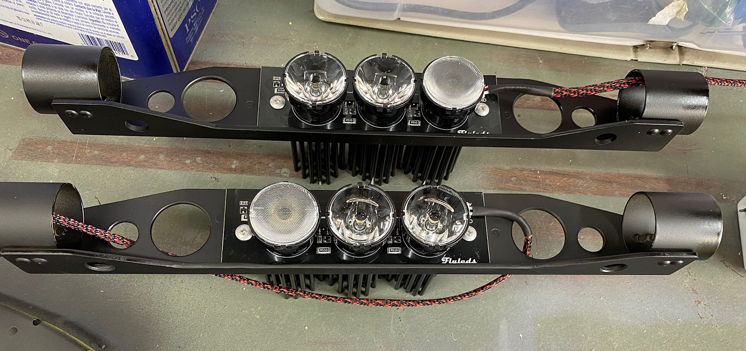
Spotlight on the Bracket
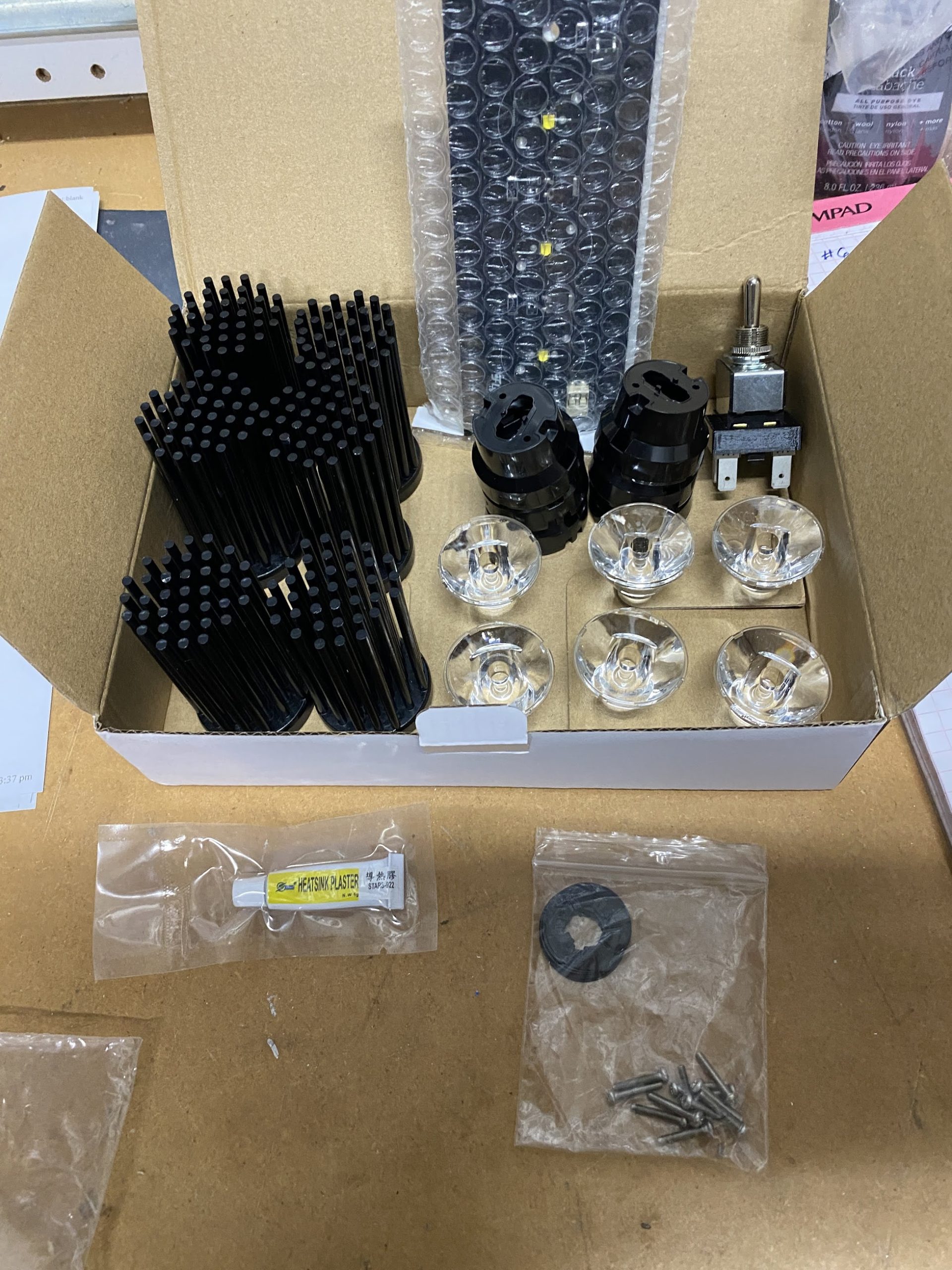
The Triple Spotlight arrives as a “some assembly required” kit from Flyleds, no more difficult to assemble than snapping a few LEGO blocks together. The base for the spotlights is a 6×2.4-inch aluminum board with a printed circuit and three Cree LEDs on the front side. The back side is flat and unfinished—perfect for helping transfer heat produced by the LEDs to a mounting bracket. It has two mounting holes, and their location is my only gripe because they are too close to the “porcupine” heatsinks on the back when assembled and don’t leave room for a nutplate. The assembly kit includes a small tube of heatsink compound which you spread thinly on the heatsinks and then sandwich the board between them and the three lens holders. Wait 10 minutes for the compound to set, snap the lenses into position and you’re done. Really simple and keeps the lights affordable.

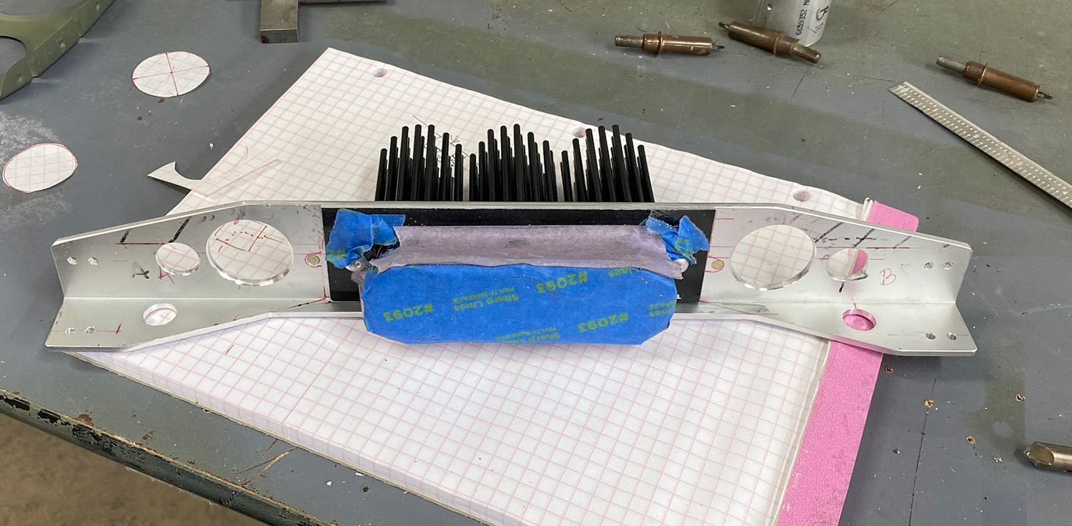
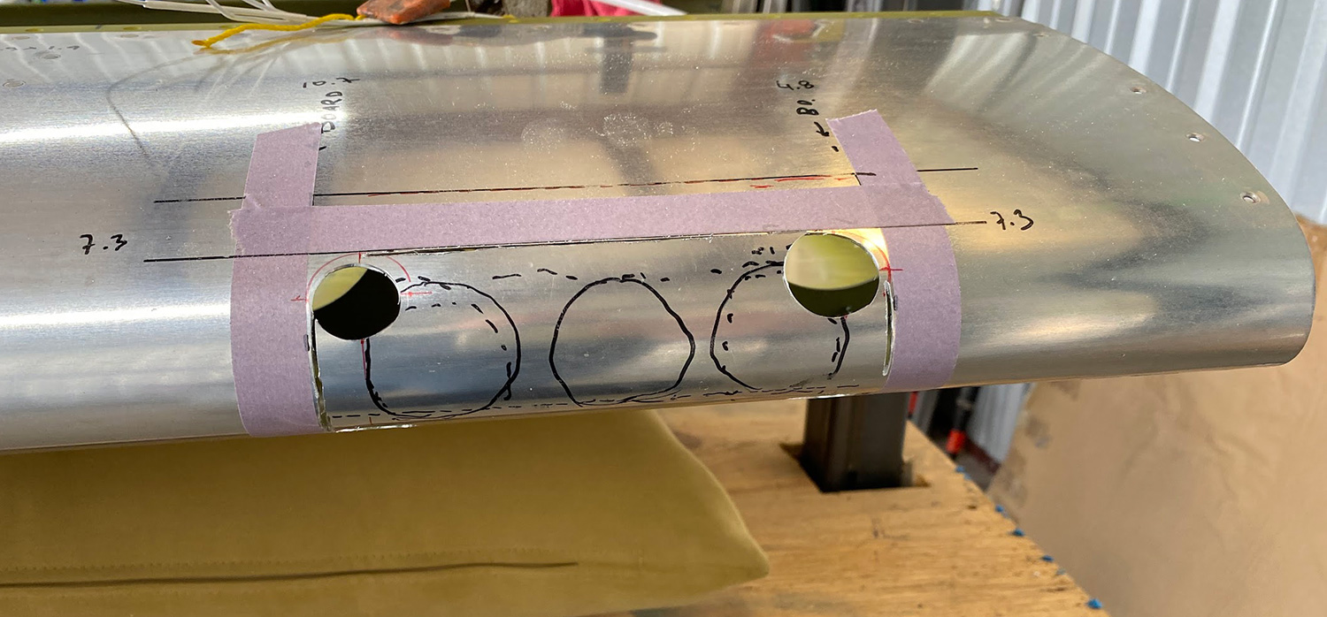
The aluminum board can be trimmed down to 1.6 inches high which is great because I wanted to have a small aperture in the leading edge. I also wanted the light to be adjustable vertically, so I built a bracket that fits between two leading edge ribs and uses the forward lightening holes for mounting. This approach lets me adjust the light without removing the acrylic lens. Anti-chafe tape between the tube and the nose rib helps make a tight fit and assures that the mounting bracket won’t rattle around and enlarge the hole.
The bracket itself is made from 2″ x 2″ aluminum angle with two short sections of 1.5″ O.D. aluminum tubing riveted to its ends and several lightening holes. The angle is 14.1″ long and each tubing piece is 1.5″ long and the total length is 15.2″. Each bracket weighs 160 g (5.6 oz). The Flyleds Triple Spotlight weighs 320 g (11.3 oz) making the total weight per light fixture 480 g (16.9 oz).

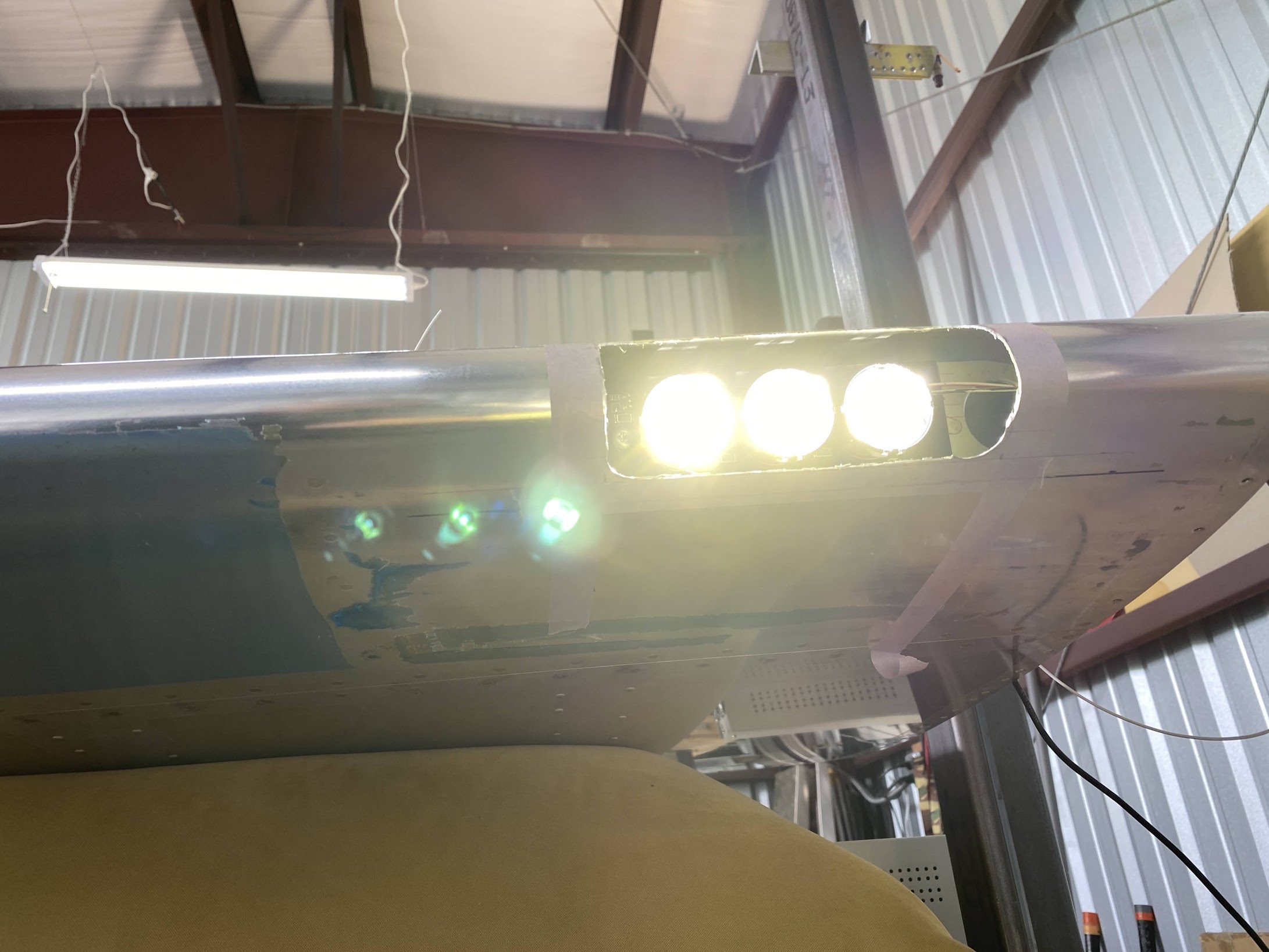
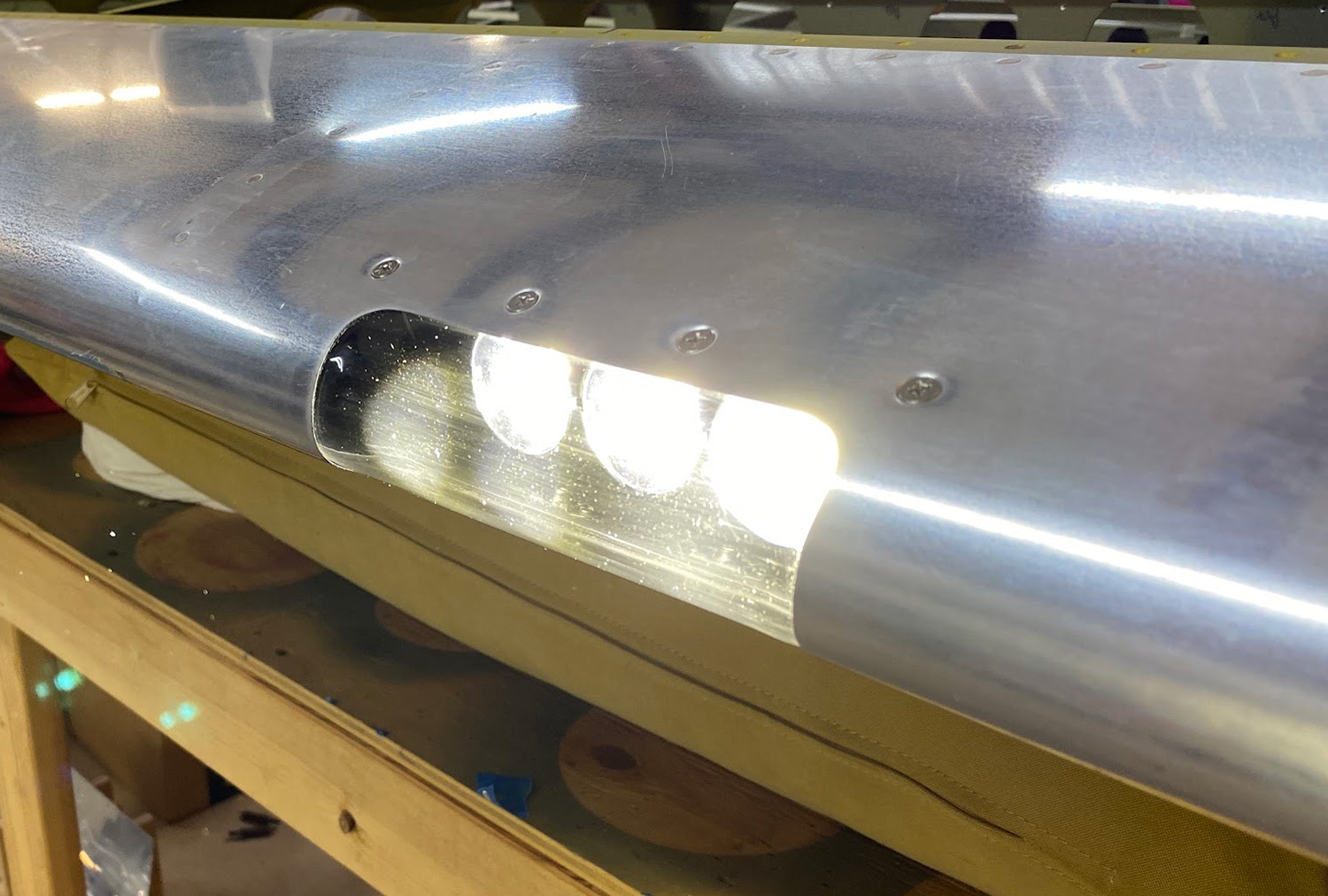
To keep the aperture small, I positioned the lights as far forward as possible, but that meant they would be close to the lens, so the smart thing to do was to test whether this would heat up the acrylic too much. Turns out it’s not a problem—I placed the lens right in front of the lights for 30 minutes, closer than they’d be in the final position, and the acrylic lens didn’t even get warm so I’m certain the LEDs won’t burn three holes in it.
I also wanted to know if either acrylic or polycarbonate sheet would be damaged by a fuel spill, so I cut two samples and placed them in fuel for 20 minutes. Both came out unscathed, but since acrylic is less prone to scratching it became my material of choice.

Forming the Lens
I’d only made rudimentary bends in acrylic sheet before, just simple 90° bends for a non-aviation project where the fit wasn’t critical, but now the lens needed to fit the profile of the leading edge exactly. For the airplane, I needed to obtain a tight fit and a matching profile and it took me several attempts to get there.
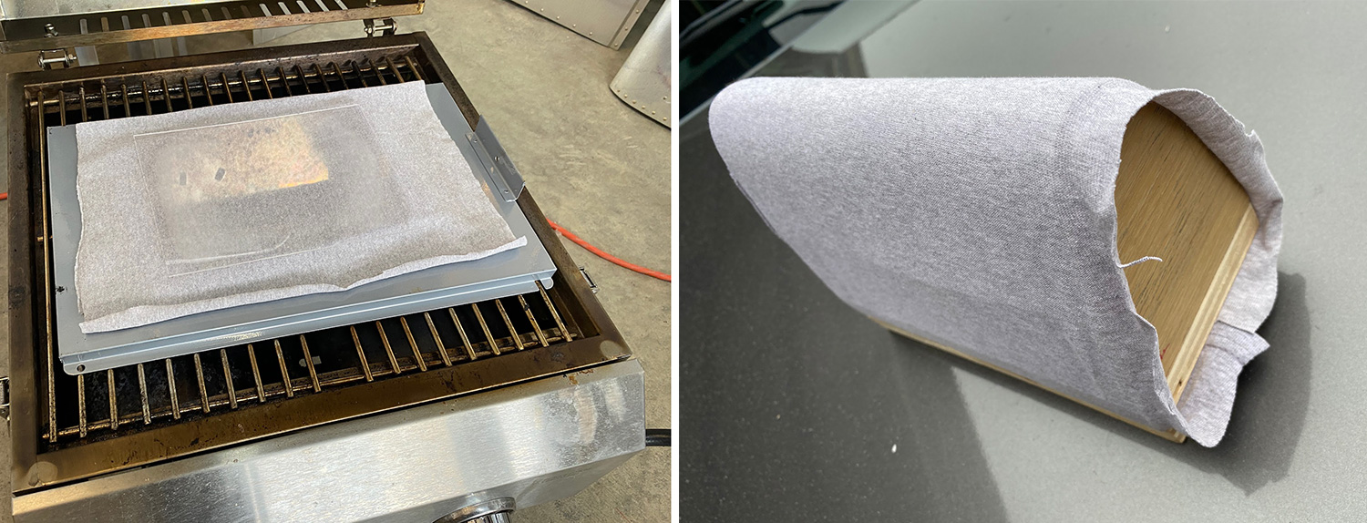
Accounting for the thickness of the acrylic, I made the drape mold 1/16” smaller than the leading edge profile so that the formed lens would fit inside the wing and then used a propane grill to heat the acrylic evenly. Through a trial and error process I came up with a way to heat the material evenly and without distortion – I stacked a sheet of aluminum foil on the grill, then the grill’s drip pan, and a piece of cardboard wrapped in cotton and laid the acrylic on top of that. When the temperature of the plastic reached 300 °F as measured with a infrared thermometer, it was ready. I put it on the drape mold and I helped it conform to the shape by draping a piece of a cotton t-shirt over the hot acrylic and pulling it down and holding for about thirty seconds.
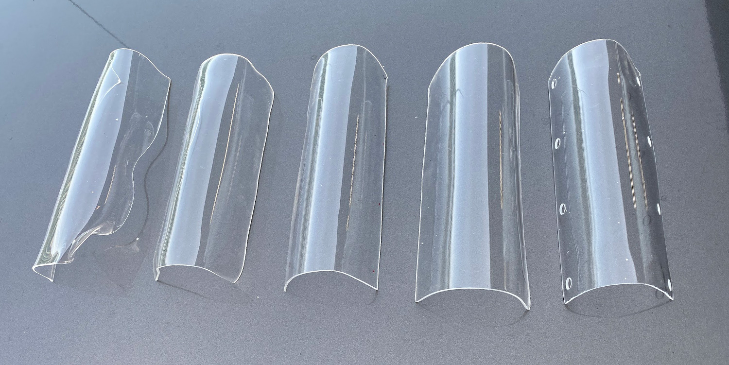
I made six pieces so that when they eventually get scratched up, I’ll have ready spares.
Lens Fit
I purposely started with an acrylic sheet that was larger than the finished lens because in the early tests I could see the edge curling slightly—enough that it would ruin the flush fit against the inside of the wing, so when I was done forming the lens, I trimmed it to final size on the bandsaw fitted with a metal-cutting blade.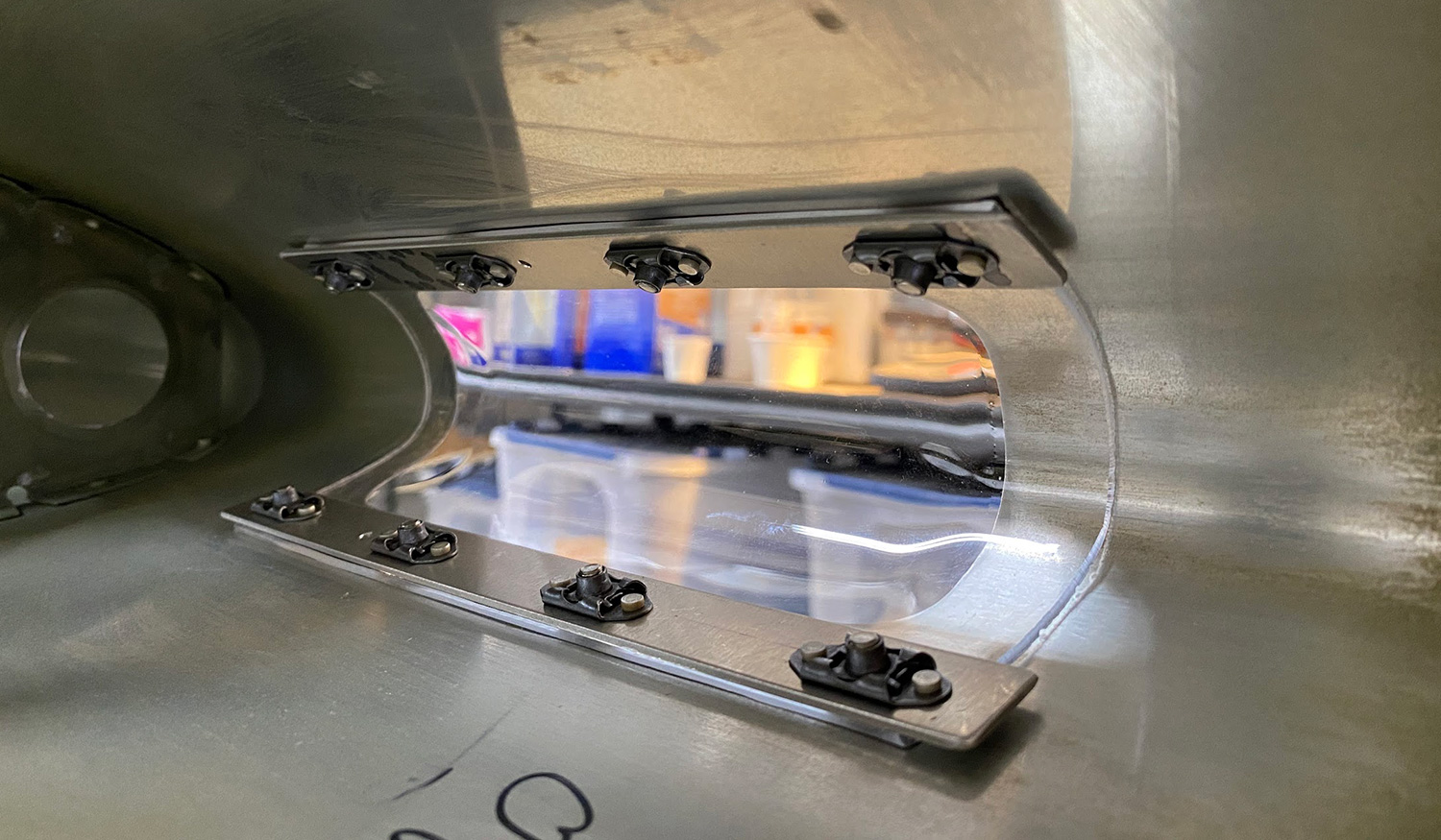
The leading edge skin is dimpled for #8 screws and the lens is held in place by a piece of aluminum bar to which I added nutplates, so I drilled holes in the acrylic large enough for the dimple to fit inside without putting any stress on the acrylic—it is held in place entirely by clamping force between the bar and skin.
Adjustability
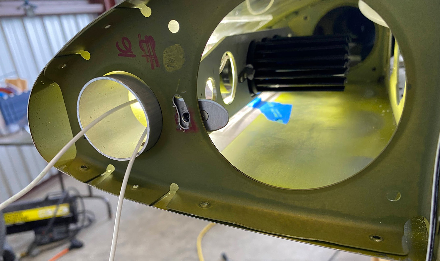
The nose ribs position the entire bracket within the wing, but it can be rotated about the two tube sections on the ends. A screw is tightened in the small lever after vertical adjustment is set. I don’t know if the light beams will need to be adjusted laterally once my GlaStar is complete, but if necessary, I can angle each LED board inboard by placing washers under the outboard mounting screw so that the light beams will intersect at some distance in front of the airplane. To make the assembly removable, I replaced the rivets that hold the outboard rib in place with #6 screws and nutplates.
This was a fun project inspired by a light bracket made by Ephraim Carter. My GlaStar is a trike, but as useful as it is, the adjustable light would be even better suited to a taildragger where it could be pointed straight for landing and down for taxi by a small servo. We can do fun stuff in experimental aircraft.


