 When I started building my GlaStar many years ago, I knew the primary mission was going to be off-airport operations since I live in Alaska. I wanted to forgo the leaf spring on the tail wheel, and replace it with a shock à la Just Highlander. I figured I would have to create my own. The problem was that I couldn’t make it internal to the fuselage because the elevator push rod takes up the space in the middle of the tail cone.
 When I started mocking up my idea a few months ago I had some engineering challenges that were going to take a while to solve. Since I have been working on this plane for 10 years I am really ready to go flying.
I have been keeping my eyes the current issues with the T3 and the bent bolts, so I checked out the Acme Aero Stinger.
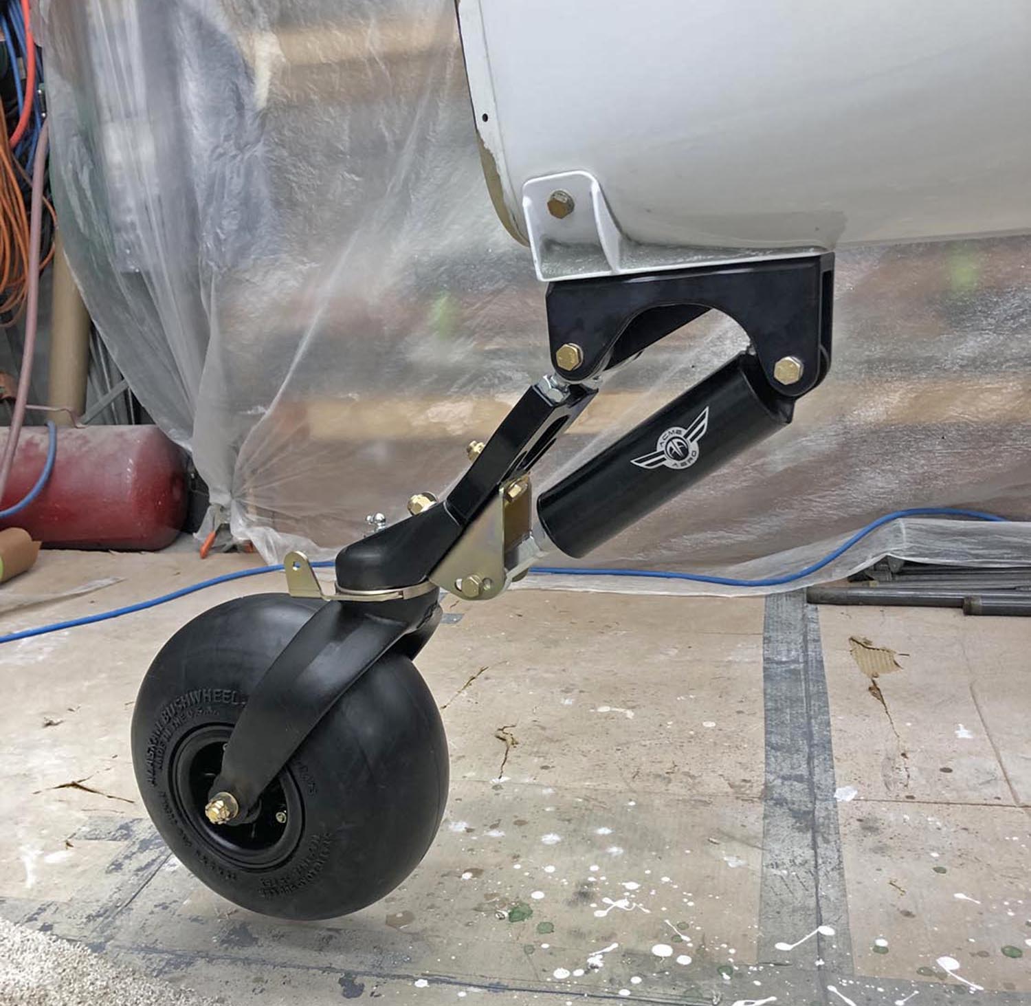
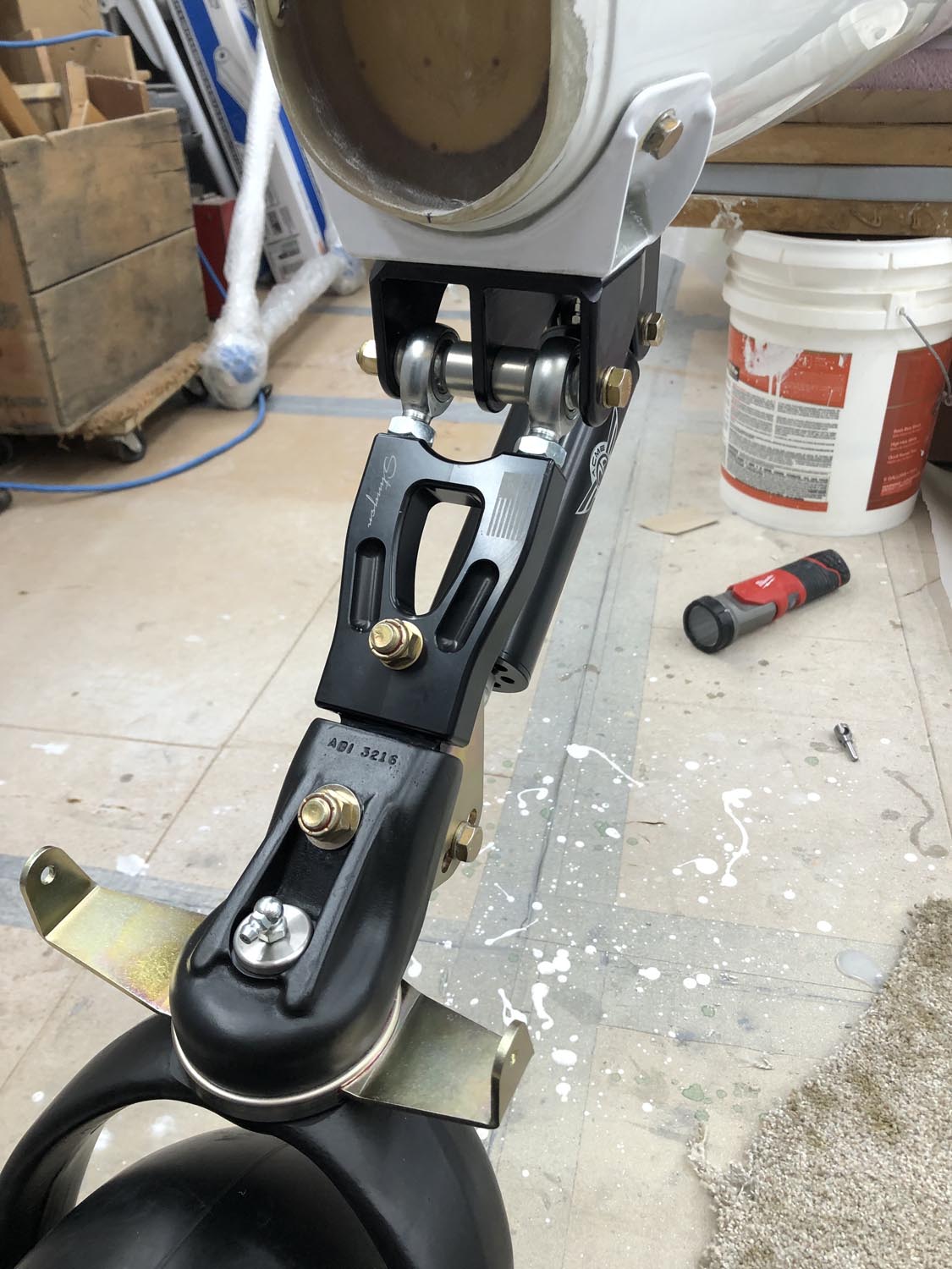
Acme Aero is subsidiary to a company that builds race cars. The “Stinger,” as they call it, is a very well built and well engineered piece of equipment. It uses a single shock mounted in the front and the back has two rod ends which allow for caster adjustment if it isn’t mounted perfectly vertically. Lengthen or shorten just one. To adjust the camber or king pin angle lengthen or shorten them both.
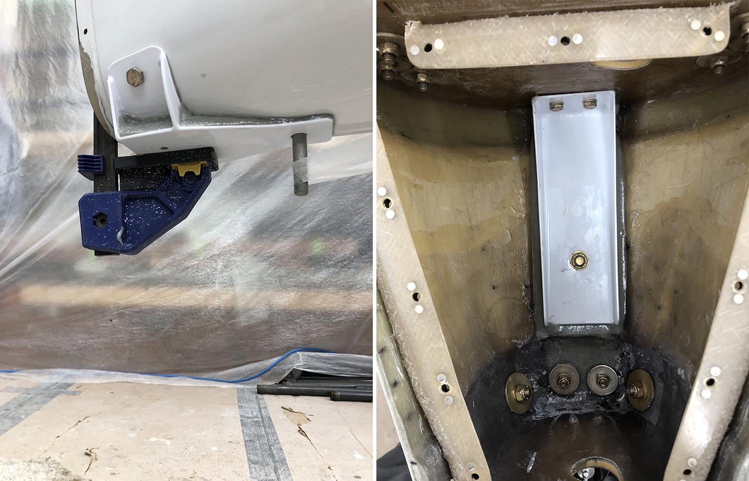
With my suspension figured out by deciding to use the Stinger, I needed to make the mount. I first made a mold of the aft fuselage, then made a part out of the mold so I didn’t have to be working on the floor.
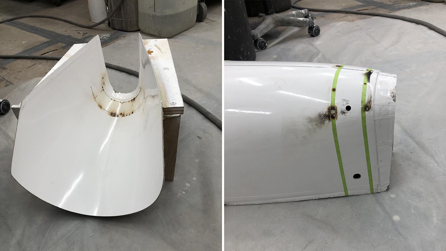
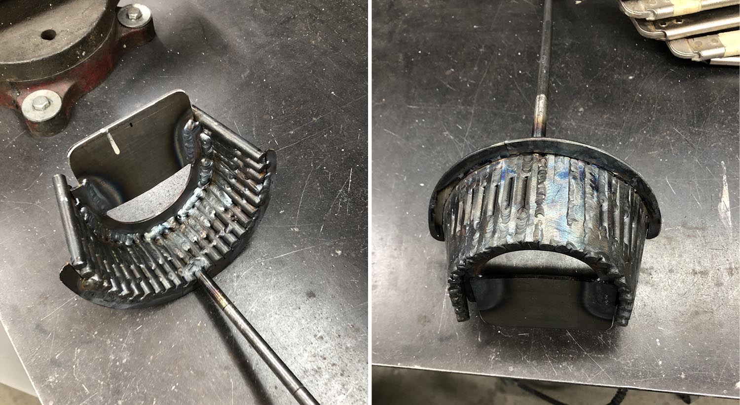
I wanted to make the shock mount out of .100 4130. The tricky part was making a metal compound curved mold. The solution was 5/16” rod cut into 4” lengths and laid in the mold and tack welded together. The long rod in the photos below was to attach the ground cable for the welder. Removed it from the mold and finish welding the rods together, I had to cut several of the welds due to warping. Once I was happy with the shape I reinforced the inside and added a guide where the part would set.
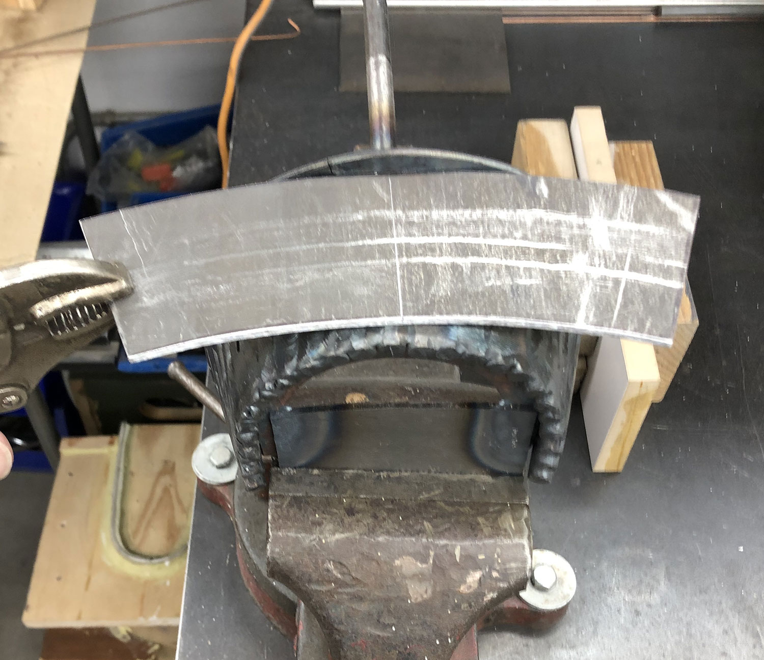
Heat forming the 4130 is easy with an acetylene torch. I did find out that you need to drill the holes before you heat-form the metal if you don’t quench it in oil—otherwise it is impossible to drill. Next step was to cut out the metal for between the curved and flat pieces.
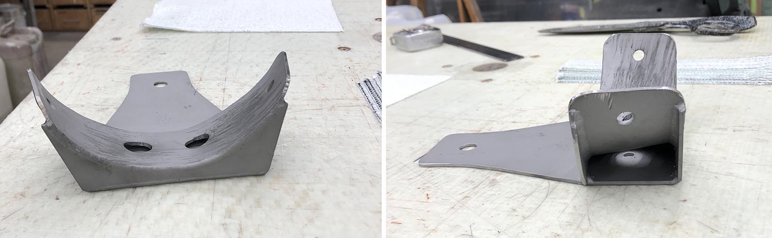
 The last piece of the puzzle was to reinforce/ transfer the load inside the fuselage to bulkhead D. I bent up a “U” channel out of .063 4130 that was 2” wide with 1” verticals, and welded an end on it.
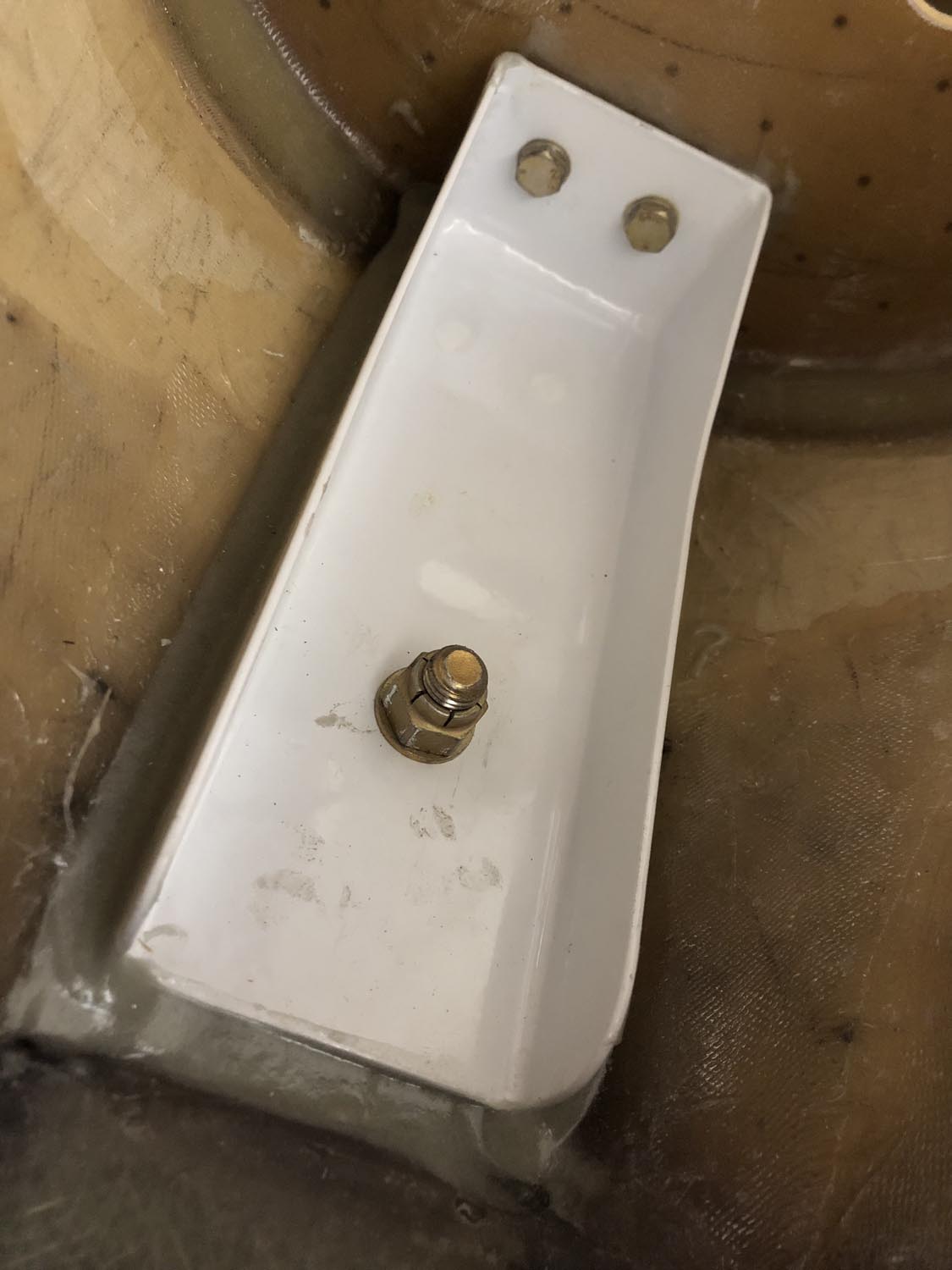
Some additional glass was applied under the reinforcement channel and in front of bulkhead “E” for the aft 2 mounting holes in the bracket. Both brackets were then bedded in an epoxy mill fiber mixture.
The Stinger and tail wheel are bolted in place. I am waiting to do final adjustments until the main landing gear is installed. The fuselage is still sitting on my shop gear while I finish a couple of details firewall forward. I am working hard to make N907TL fly by mid summer. PIREP to follow.