Submitted by Neal Garvin and Hal Mandly, Glasair Super II-S RG
This method uses a taut line strung between the two outboard hinges as a guide to align the remaining hinges
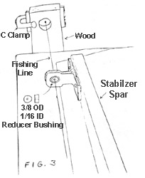
The line is fixed to pieces of wood attached to the ends of the workbench in line with the stabilizer spar/trailing edge. Reducer bushings are used to keep the line centered in the outboard hinge bushing holes and for easier positioning of the remaining hinges on the line as a guide. These bushings can be made from just about anything as long as they are concentric (ours were made of steel 3/8″ OD x 1/16″ ID x 1/4″ thick)
Position the outboard hinges-centered between the trailing edges
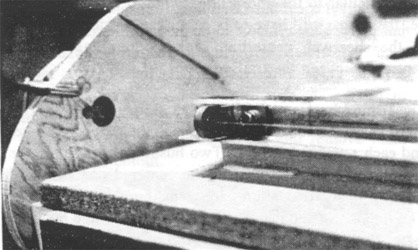
With the horizontal stabilizer still in the jig on the workbench, temporarily fix the bottom panel in place on the fixtured top panel with small weights along the spar to hold the panel in position. Use 2 or 3 layers of duct tape on the spar cap to simulate the buildup of mill-fiber expected when the panel is permanently closed. The objective here is to get the horizontal stabilizer trailing edges spaced to where they will be after final closing.
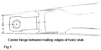
Place the two OUTBOARD hinges in their proper spanwise position on the spar so that the center of the hinge pivot point is centered between the upper and lower trailing edges (the gap above and below, between the hinge boss and the trailing edge should be approximately equal as shown in figure 1. Use hot glue or body putty to firmly attach the hinges to the spar so they will not move. (Note: if the spar shearweb is not absolutely perpendicular to the chord line, which it probably won’t be, the hinges will have to be moved up or down relative to the shearweb centerline to keep the hinge bosses centered between the trailing edges.
The fishing line is used to align the remaining hinges on the spar by threading the line through the outboard hinges and each remaining hinge. Two bushings are used in the outboard hinges to keep the line centered and the third bushing is used to align each remaining hinge. Note: The line is not “attached” to the outboard hinge brackets as they will not support the tension of the line.
Rig the line and support brackets
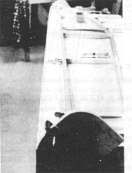
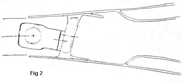
Attach a piece of 1/2″ plywood or equivalent (2×4 etc.) to each end of the workbench in line with the hinges as shown in fig 2. Make sure the wood pieces are securely attached as they will support the line pulled tight between them. Drill a I” (approx.) hole through the plywood in line with the hinge holes to run the line through and allow for adjustment.
Make 2 small adjustment/line support blocks (1/2″ plywood. masonite, 1/8 aluminum etc.) with a small hole drilled just large enough for the line to pass through. Tie a knot in one end of the line so it will not pass through the adjustment block. The other end will be threaded through the hinges and bushings to the other end of the stabilizer where it will be fastened to the other support block.
Temporarily clamp one adjustment block to the outside of a support block with the hole lined up with the centerline of the hinges. Thread the line through the adjustment block, the plywood support block, three reducer bushings, the remaining 4 hinges and through the other end hinge to the support block. Pull the line tight to insure it does not sag and tie it off on the other end of the work bench. (Note: saw cuts made in the edges of the adjustment block work well to hold the line if it is wrapped several times around the block through the cuts – tying a knot in the end does not work well and will be cumbersome as the line will be removed and re-threaded several times.)
Position and align the remaining hinges
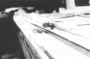
Slide bushings into each of the outboard hinges to hold the line in position. Temporarily secure the remaining 4 hinges to the spar with clamps or hot glue so they do not interfere with the line. With the reducer bushing’s installed in the two outboard hinges, move the line adjustment blocks to center the line in the outboard hinge bushing holes to remove any unnecessary pressure on the hinge from the line and to insure the line is centered (the hole should be slightly larger than the line to allow the line to “float” in the hole without touching the sides).
Using the third reducer bushing, adjust the position of each remaining hinge on the spar so that the line passes through the center of the hole. Be careful to check that the line is not resting on the edge. of the bushing hole. You should be able to move the line in all directions (up, down, back, forward) inside the 1/16″ bushing hole. It may be necessary to pad the hinge out to get proper fore and aft alignment. It may also be necessary to shim the outboard hinge brackets to allow the inboard hinges to align properly. We clamped the hinge in place over a mill-fiber mix with 1/16″ wide strips of .025 aluminum under the corners of the hinges to maintain the proper shim thickness while it cured.
You may find that the hinges do not fall exactly on the centerline of the spar if the spar shearweb is not exactly perpendicular to the stabilizer cord line. This is ok as the objective is to align the center of the hinge pivot points from end to end along a straight line axis and to have the hinge pivot points centered between the upper and lower trailing edges as best possible.
Drill, install nutplate and mount the hinges
With all the hinges properly aligned, drill through the spar using the hinges as drill guides and continue with the nutplate installation, D ribs and closing of the stabilizer. Mounting the outboard hinges first allows checking the alignment of the remaining hinges as you go. If any misalignment is found after bolting the hinges in place, additional shimming can still be done to correct it.
Note: We recommend re-attaching the hinges and leaving them in place when closing the stabilizer to allow the gap between the hinge boss and trailing edges to be checked both prior to and during closing.


