Purpose
I have been considering a modification to the fuel vent system on my Glasair Il-S. I know this statement makes you want to rush to the phone and notify your favorite tabloid for the scoop money, but hold on, there’s more. The need for the modification comes from a deficiency in the Glasair fuel vent configuration which may not be unique to the Glasair. Studying the problem revealed to me many options which should be considered in any design. What I am trying to do here is discuss some of the options I considered, pros and cons of each, and provide you with food for thought when designing or building your dream ship.
Background
All the Glasair series of aircraft have very similar fuel systems. The fuel capacity of the Glasair III is larger than the I or II due to extra bays in the wing, and many builders have stretched the capacity of their tanks by placing the fuel caps further outboard thereby decreasing the airspace in the wing tank, but other than that, they’re identical. For the purpose of the vent system, there is absolutely no difference.
The basic design is shown schematically in Figure 1. The main (or wing) tank is a single tank, located in the forward D-section of the wing. It is a wet wing meaning no bladders or separate tank structure is used. The wing skin and spar are the actual tank walls. The tank extends from the most outboard rib to the opposite most outboard rib. Numerous baffles are located along the span (which double as wing ribs). The most inboard symmetrical pair of ribs have very small transfer passages along with large flapper-door style check valves to permit feeding fuel from both wings to the fuel pickup but restrict (not prevent) flow from one wing to the other during uncoordinated flight. The fuselage (or aux) tank is located aft of the firewall above the pilot’s feet, behind the instrument panel (and instruments). It too is “wet” in that the firewall and fuselage skin make up two of the six walls. The remaining walls are made of the same materials and fabricated in place by the builder. The feed system consists of a selector valve fed independently by each tank which in turn feeds the electric boost pump.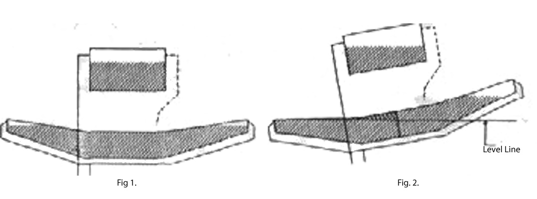
The stock vent system is also illustrated schematically in Figure 1. The fuselage tank, and each wing tip is vented to a common manifold under the wing, then overboard. A second line is extended overboard for redundancy. Imagine a bug strike (causing fuel starvation due to pump cavitation, followed by engine failure, probably at low altitude since bugs aren’t turbocharged, even to 3000 AGL) causing the destruction of your, I mean my ego amplifier. The dashed line is a vent from the fuselage tank to the stock float type fuel gauge. During fabrication and installation, care should be taken to run each line so that puddles will not form in the lines. Allowed to dry, this would eventually block the line.
The deficiency in this design is illustrated in Figure 2. When parked full, the Glasair tends to drain mass quantities of fuel through the vent system unless it is completely level. All airplanes do this to some extent, but the Glasair design aggravates the problem tremendously. The figure illustrates a 10′ tilt (a little extreme but it makes the picture clearer). The wing is not to scale, but the relative positions of the corners of the wing and fuselage tanks are close (on the Glasair, the lower skin at the tip is nearly level with the upper skin at the root). Notice how much fuel is above the level line. This will eventually leak out through the vent system. Almost half a tank! Now that I have described the problem, let’s talk about several solutions.
Solution 1 (Piper Style)
Those of you that have flown the PA-28 series of Pipers, know that the wing contains 2 fuel tanks. Splitting the Glasair wing tank will greatly reduce the problem. Shown in Figure 2 is the result of this fix. By isolating the left and right sides, the amount of fuel that could escape through the vent is reduced to the crosshatched area. This is a small fraction of what it was previously. For Piper, this worked even better because the vent lines could be made to run further up the dihedral before turning Earthward since the tanks don’t go to the tips. This solution has been used in many Glasairs, but there are three disadvantages. First, it takes time to build the bulkhead but you could get rid of the check valves), install a second sump, drain, fuel pickup and fuel gauge. Second, it takes money to buy all that stuff and a new valve that is not included in the kit But time and money are part of the business. The real problem should be familiar to all you Piper pilots. Fuel management workload is increased. The fuselage tank in the Glasair is only about 9 gallons, about 50 minutes for an 10-360. A very nice IFR reserve. Therefore normal ops would be to fly only on the wing tank until it is empty. If the wing tank is divided, switching tanks to keep balanced would be required as in Pipers. I know, you test pilots are saying that’s not workload, but every little bit helps. I have read of plenty airplanes running out of fuel with a full tank on board (trapped fuel or plain stupidity). A both setting on the valve is not an option on low wing airplanes. If one tank goes dry, the pump would gladly suck air rather than fuel up the hill to the engine. With high wing planes gravity pulls the fuel to the pump in preference to the more buoyant air. Though this solution will work to reduce the problem, some fuel can still escape through the vents, and complexity and workload are increased.
Solution 2 (Vent Lines – Checked)
Many Glasair builders have thought about or used check valves at the wing tip ends of the vent lines. Not just any valve will work though. Remember, the vent system must let air in and out of the tank. if flow is limited to air coming in as fuel burns down, the tanks will trap high pressure air from low altitude while climbing into low pressure air at high altitude. This could easily rupture the tank. There are valves made that will allow air to pass while blocking fluids. They are, of course, more complicated and more expensive. Stoddard-Hamilton (the Glasair kit manufacturer) likes this method and is testing valves which they plan to sell to builders. I worry about water entering the valves and freezing, causing the valve to stick open fbad) or closed (worse). And what if the tank is very full, parked on a hot ramp and the fuel expands to fill the entire tank (no air at all)? Remember KISS and Murphy’s Law. Check valves add complexity (a.k.a. failure modes) and expense, but at least the workload is not increased.
Ed. Note: Doug may have not been familiar with our fuel vent float valves we have just developed at the time he wrote this. The valves take all of these concerns into account. A float raises and lowers with the fuel level to close or open the fuel vent. With the tanks completely full, or in case of the valve freezing or sticking, there is a check valve that opens and allows the engine to still draw fuel from the tank. They have a pressure relief valve that would relieve any excess pressure that may build due to thermal expansion on a hot ramp.
Solution 3 (Work Around)
Some Glasair operators just don’t park it full. Fill the aircraft before flight rather than after. Or just make sure it’s parked level. This is the epitome of KISS, no mod at all, but lots of things could happen that would prevent this from working. I have been told that condensation in the tank is not really a problem since fiberglass insulates much better than metal so the temperature inside the tank does not change enough to make condensation of the vapor probable. I’m not sure I believe this though. What if you fill the tanks and then don’t fly for some reason? What if you want to go fly at 6:00 a.m. and need fuel? This is not really a solution at all, especially if the aircraft is still in construction.
Solution 4 (Fashion Statement)
Winglets are the rage. All the new airliners have them. The C-17 has them. The E-Z’s have them. The Voyager had them for a while. I’ve even seen ultralights with them. The B-2 doesn’t have them, but then that’s a plane only a contractor could love. Why not the Glasair? Some Glasairs can be seen sporting these so called efficiency enhancers. Of course wing tip designs are about as varied as Long E-Z noses. Some of the winglets on Glasairs are probably for aerodynamic reasons, but I talked to one guy that just wanted a mast for his fuel vent, and decided to “dress it up” (disguise it is more like it). The vent lines simply exit the tank and run up this six inch mast and terminate at a NACA scoop. The lines cannot be pointed aft as this may siphon fuel in flight. Pointing them into the wind (a NACA scoop makes the installation flush) will prevent siphoning but will collect rain and ice like crazy. This does not happen if the lines point down since gravity drains what the forward motion collects. This also requires a lot of extra work to design, fabricate and build (remember, this is a KIT plane, I am trying to avoid reinventing the wheel when possible). Fashion is a matter of taste, and you may do what you like, but I hate winglets almost as much as I hate canards. I also plan to fly when I decide to fly, not when the weather decides to be good.
Solution 5 (Work Around 2 – The Post-Flight Snorkel)
Another work around solution would be to install a “vent line extension” as part of the post-flight checklist. Fabricate a line which fits snugly onto both external vent tubes, runs around the fuselage until it is the highest point in the vent system, then turns 180′ just far enough to keep the rain out). This upside-down “snorkel” can be installed after flight just as a pitot cover would. During preflight, it would be removed and stored in the aircraft (use flexible tubing for compactness). The only disadvantage would be that fuel would spill out of the flooded vent lines when the device is removed, and the pre-flight would have to be performed on level ground. This solution is ideal if the aircraft is already built.
Solution 6 (Stroke of Genius)
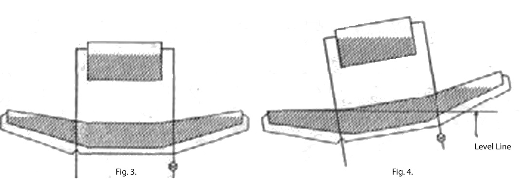
Figure 3 is my favorite solution. Notice the vent to the float type fuel gauge is gone. Not a requirement for this solution to work but it does make it more elegant (I’m planning on using a capacitance fuel probe). By plumbing the lines as shown, the wing is vented into the fuselage tank. Any overflow will flow into that tank, and air will be drawn from that tank. Only the fuselage tank is vented outside. The valve I’ve drawn is included to drain the lines since the WILL trap fuel (up to the level line shown in Figure 4). The redundant outside vent is shown downstream of the valve. In this configuration, open the valve and you have the original design. Close the valve and you are drip proof until the fuselage tank overflows which is not a concern in normal ops. The big drawback is the trapped fuel. With the valve closed (normal ops), fuel trapped in the lines will act to plug the vent. Enough negative pressure must be developed in the tank to siphon the fuel back into the tank. The vertical distance from the lowest point in the vent system to the tip of the wing on the Glasair is about 13 inches. My calculations show about .365 lb./in2 of vacuum will be required to draw the trapped fuel up into the tank. Even a low pressure fuel pump could handle 10 times this amount. But the pump will not see even that low amount. Estimating that a maximum of 20 feet of 1/4″ i.d. tubing were filled with fuel would mean the vent lines were holding .05 gallons or 6.5 oz. of fuel. A mere quart of fuel remaining in the tank is 5 times the amount in the vent lines, so the siphon pressure would easily draw the fuel back into the tank. Of course, as mentioned in the background discussion, the lines should be drained so fuel will not dry leaving residue which may restrict or block the lines (I have been told that this is not likely by competent authority). The real purpose of the valve is to periodically drain the vent lines. The valve can be the sump drain type, for use during post-flight, or manually operated for use in-flight or post-flight. If the former is used, be sure to re-plumb the redundant overboard vent. If the latter is used, then checklist items are in order. The valve would of course be closed for refueling, parking and pre-flight ground ops. Many choices are available for when the valve should be opened. Just before take-off, sometime after burning down some fuel, or as part of the loss of power emergency checklist (if the redundant overboard opening is as shown in Figure 3) are some of the choices. Just make sure it is covered in the checklist and try to not make it a significant workload increase.
It’s well past time to shut up about this trivial thing. I just wanted to point out how such a trivial thing can get complicated and remind you of how many trivial things make up aircraft design, construction, and operation. I also wanted to present some of the ideas that I ran across while investigating this little design deficiency. Maybe you can use them in your application. If you have a solution I haven’t thought of or know a reason why solution 6 would not work, please let me hear it. None of the solutions I presented are the perfect solution, all have their advantages and disadvantages.
What’s your solution?
Answer to Doug’s question:
Submitted by Charles D. Mason, Glasair 1 TD
After reading Doug Dodson’s two and one half page master’s thesis on fuel vents for the Glasair in the last newsletter, I just couldn’t resist the urge to answer Doug’s final question “what’s your solution?” My solution requires no float valves, pressure relief valves, winglets vents, wing-long tubes, vertical loops of tubing, etc. From the beginning I wanted an airplane with long range so I moved the fuel bulkheads as far out on the wing as possible. This did two things (1) it provided room for 45 gallons of fuel in the wing ahead of the main spar and (2) it gave me the problem of losing gas out of a vent when the plane was parked any way but perfectly level. The leakage problem was solved by using horizontally installed one-way valves (with the springs removed) in the wing tip vents.
The next thing to consider was what to do about expanding gasoline in full tanks sitting in the sun. This was addressed by connecting the wing tank to the header tank. Two quarter inch tubes were glassed in to the top skin of the wing tank near the center. Two tubes were installed in the header tank extending from the inside top of the header tank to an inch below the bottom. The pipes from the header tank were connected to the pipes in the wing with fuel-rated tubing and clamps. The end, that’s it.
The beauty of this arrangement is that the fuel vents in the header tank provide a backup venting system in case the wing vents get clogged and the wing tip vents will provide air to either tank if the header tank vents get obstructed.
The header tank vents are in the hot air stream from the engine and are unlikely to ice up. As an added bonus the expanded fuel which would ordinarily leak overboard from the wing tank winds up in the header tank. This system of four interconnected vents has given flawless service for eight and one half years and over 1100 hours of operation. The one way valves are made of aluminum and come from Kepner Products Company of Villa Park, Illinois.
Ed. Note: Chuck’s idea works great for the Glasair I’s without a stand pipe fuel gage or when a Vision Micro System capacitance fuel probe is used to measure the fuel, however, readers must be aware of the differential pressure sensitivity of the stand pipe fuel gage, used on Glasair Us and Ills, that makes it very critical to the vent system design. The advantage of the stand pipe is that it does give accurate fuel level readings through-out the dihederal of the wing when the stock G-1I/1II vent lines are installed. Fuel spillage can be prevented by the use of the new Fuel Vent Float Valves for this type of system.


