 Soon after purchasing my GlaStar, N757C, from her original owner and builder I contacted Glasair Aviation and inquired about the price of factory-built auxiliary fuel tanks. The price in the options manual that the original builder passed along to me was $895 in about 1998, so you can imagine the sticker shock I felt when I read their current quote at just under $2000 for the tanks. A year went by and I still just couldn’t bear to part with that much cash, so I decided to build my own.
Making things is fun and this could be a new learning adventure! I started out by printing a copy of the auxiliary fuel tank installation instructions found in the document library at glasair-owners.com. This included a parts list that was very helpful, but some specifications were not shown. Unfortunately, there is no picture of the entire tank shown in those instructions. I searched the forum quite thoroughly and found lots of discussion, only a few partial pictures, and some useful information. The installation instructions were quite helpful though, and I read them over many times until I felt I had a firm grasp of the task I would be undertaking.
After some internet research, I found a good article from the EAA and some helpful personal experiences and advice from other builders in the forum. My plan was to make a tank that would be curved on both the top and bottom for maximum capacity then cleco (special clamps used in sheet metal work) it together just enough that I could take it to a professional welder and have all the seams TIG welded.
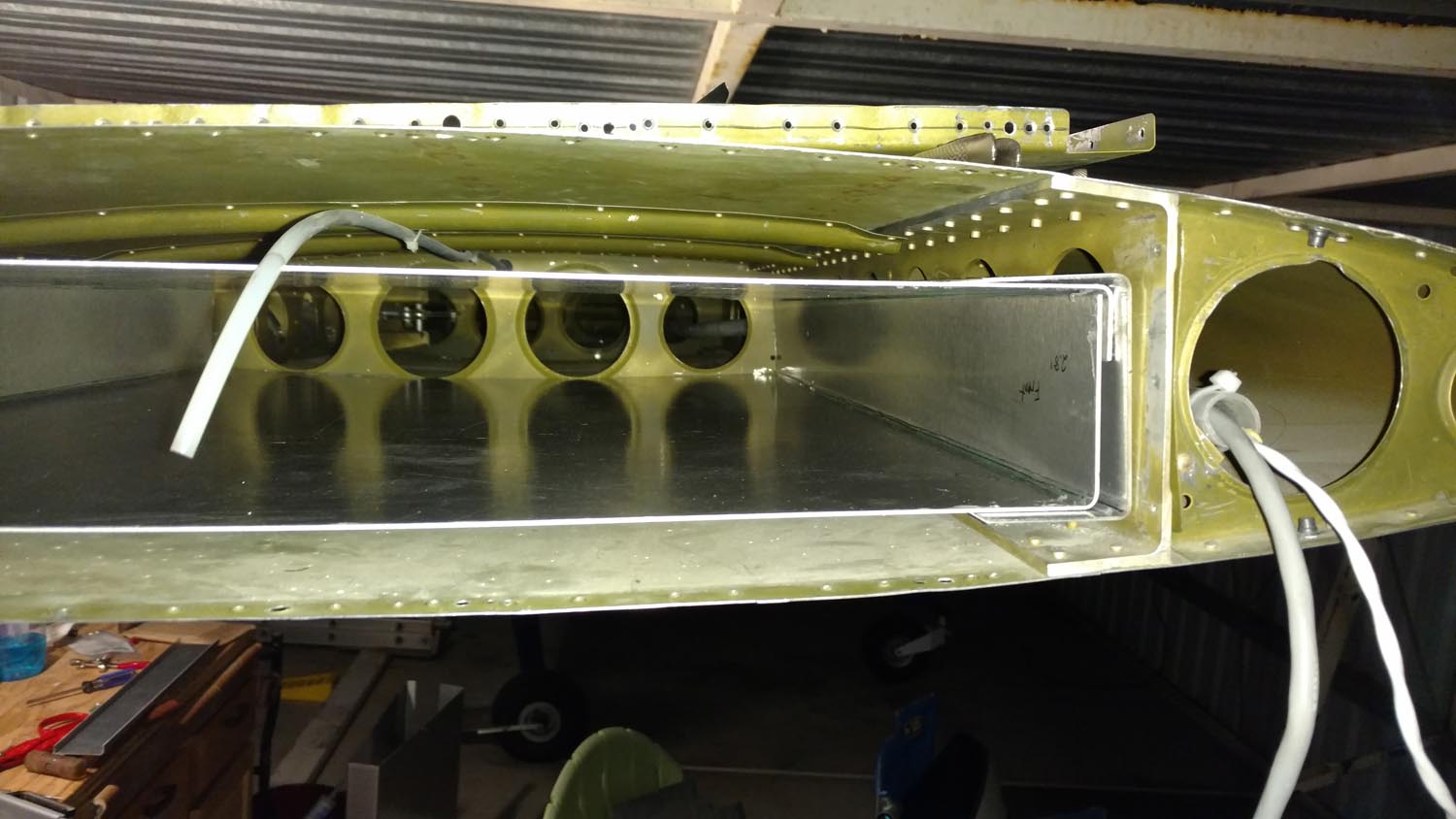
The rivets that hold the most outboard wing rib were carefully drilled out, and the rib was removed. A template was made out of a piece of 3/4″ plywood to just fit within the hat sections of the wing. The rib and skin were dimpled so that the rib could be put back using #3 countersunk machine screws with nyloc nuts. This allowed the plane to be flown while the project was taking place and made for easy removal of the rib many times throughout the project duration.
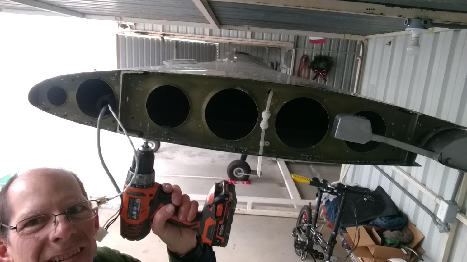
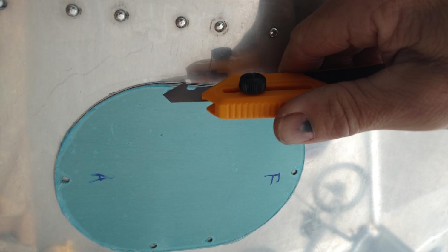
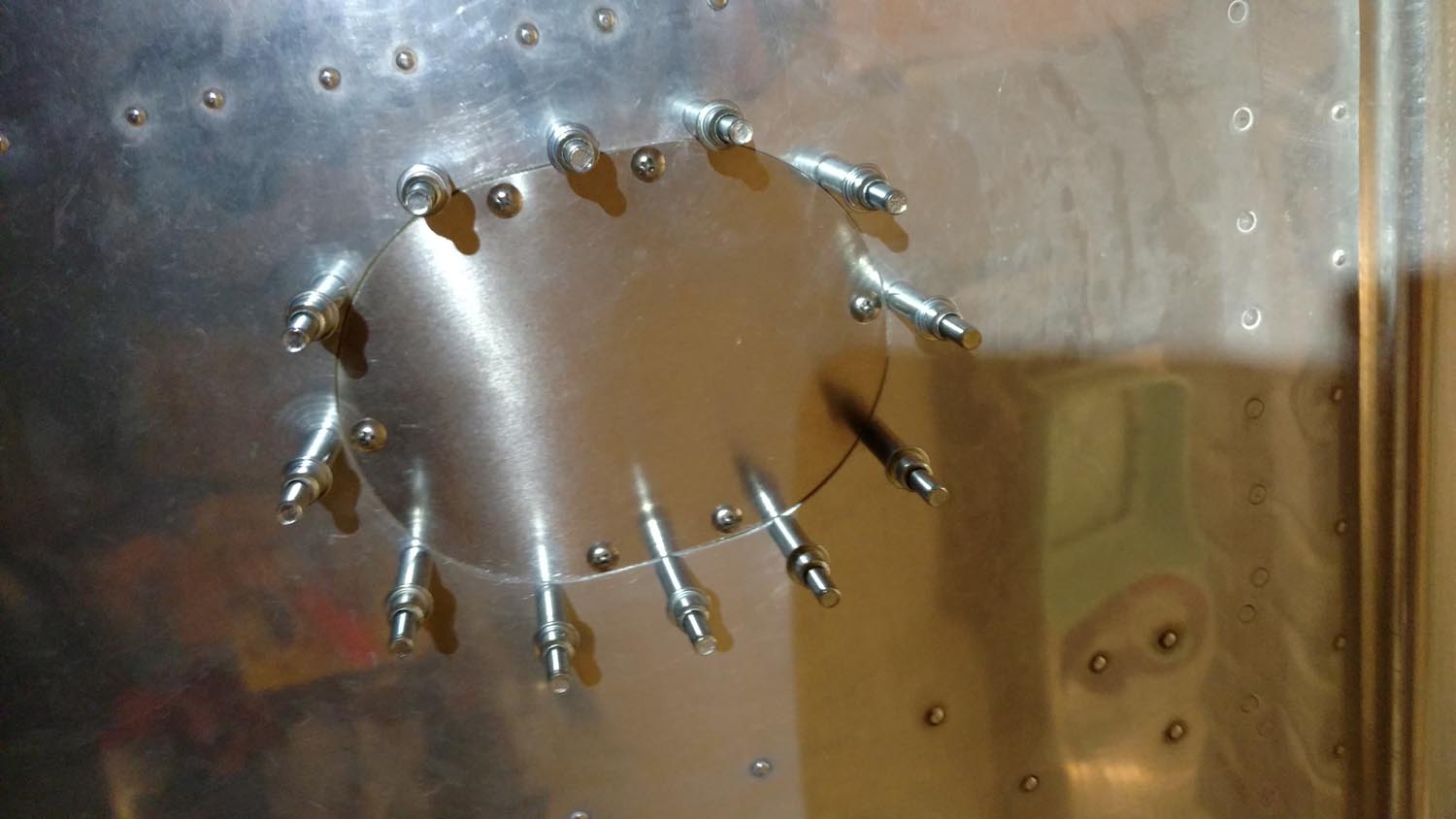
A plastic wiring conduit ran right through the area where the tanks were to be located and needed to be re-routed forward of the front wing spar. Access to the inboard end of the tank would also be very limited so an access hole was created. This made attaching fuel lines and future removal of fuel screens much easier. While there are companies such as MyKitAirplane.com that sell the necessary parts for creating the access cover, I chose to make them myself, cutting out the hole in the wing skin with multiple passes from an OLFA knife with PB-800 blades. Two YouTube videos that were a tremendous help included, adding inspection panels and cutting openings in sheet metal.
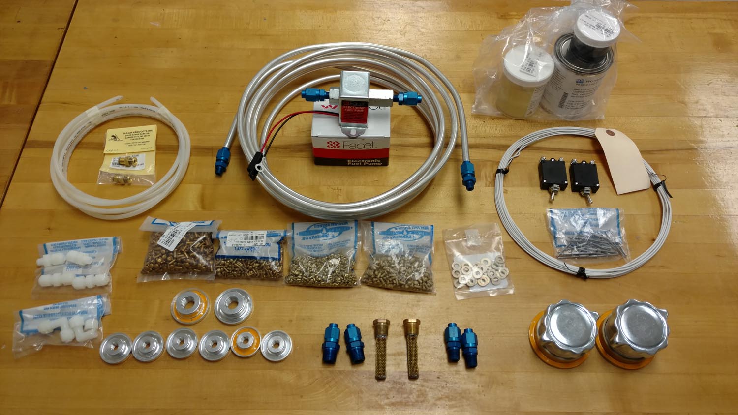
Using the parts list included in the installation instructions as a starting point, parts were researched, located, and a firm plan of attack was developed. Measurements were taken and drawings were made. The next stop was the welding shop.
Best laid plans
I discussed my plans with the shop foreman and he wasn’t very receptive. I’ve used this shop many times for other small projects over the years and respect the foreman’s knowledge and opinions. Everything he told me was not what I wanted to hear. With me bringing him the tank held together with clecos and ready to weld he estimated about 8 hours per tank! Their shop time is $90 an hour. I went to a couple other shops and was similarly dissuaded. I’m a decent welder but I’ve only tried TIG a couple times and without much success either. This is something that takes the proper equipment, time, and experience to become skilled at doing, especially on aluminum. I’m always up for a challenge and many planes don’t have welded tanks. I made up my mind that these tanks would be riveted.
With a week of vacation ahead, all the parts were ordered in advance. Welded tanks are commonly made from .050 thick 5052-H32 aluminum sheet. Not having much sheet metal experience, I didn’t realize I could go with a bit thinner material since I would be riveting, instead of welding. The tanks would have been lighter in weight and a bit easier to work with.
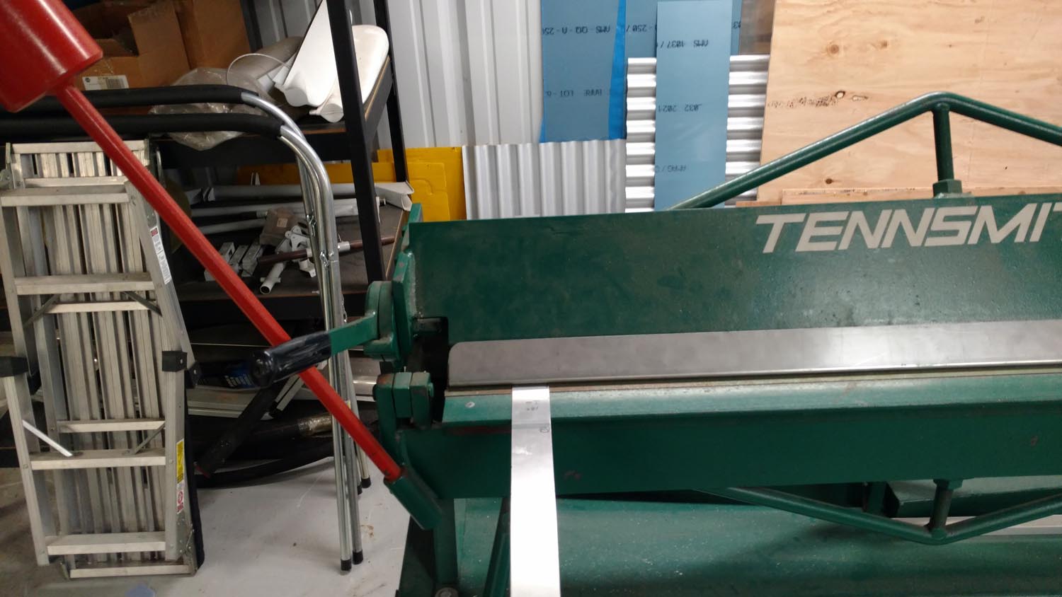
An EAA friend offered use of his hangar and shear and brake. Upon explaining what I was going to make, he heartily advised that I make the tank rectangular in cross section to avoid putting stresses in the metal that could cause cracks, as well as simplifying the project tremendously. This was supposed to be a learning project and I don’t like learning things the hard way. I wasn’t happy about the reduced capacity but I reluctantly took his advice.
The bends
The first step in bending and cutting the metal was to draw layout lines on the sheet metal. Bending of material forms a radius around the corner which must be accounted for or your sheet will end up the wrong length. Watching some videos on YouTube revealed there are some handy formulas to help calculate this for 90 degree bends:
Bend allowance = (1.57) x (bend radius) + (0.702) x (material thickness)
When selecting a bend radius, be sure the sheet metal brake you are using is capable of making that radius and consult a table to make sure you are not exceeding the minimum safe bend for the alloy and thickness of metal you are bending. In other words, a thick piece of brittle alloy will be weakened or even crack or break if it is bent in too tight of a radius.
These tanks were made using a 1/8″ bend radius and .050 material thickness.
Bend allowance = (1.57) x (0.125) + (0.702) x (0.050)
Bend allowance = 0.23135
Setback = material thickness + bend radius
Setback = 0.050 + 0.125
Setback = 0.175
After making these calculations, bend tangent lines can be drawn on the material. Let’s say you want your first bend to be 6″ in from the end of the sheet. Take 6″ and subtract the setback:
6 – 0.175 = 5.825
The first bend tangent line would be 5.825 inches in from the edge of the sheet. Add the bend allowance to the 5.825 and you have the location of the second bend tangent line. These lines represent the start and end of the bend radius. When working in the middle of a sheet you must subtract 2 setbacks. If the calculations are performed correctly, it actually takes less material than if the corners were not rounded. The length of the sheet for each of these tanks with 4 bends required almost 1/2″ less material than if the corners didn’t have any radius.
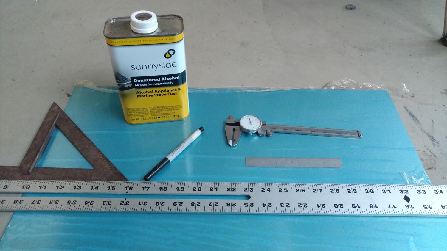
A dial caliper and extra fine tip sharpie marker were indispensable during the layout process. Alcohol or acetone was used to erase any errors. A sample piece made from scrap material was bent first for practice and to verify all measurements were correct. Be sure to cut the sheet to length before bending as there likely won’t be enough clearance to put it in the shear afterward.
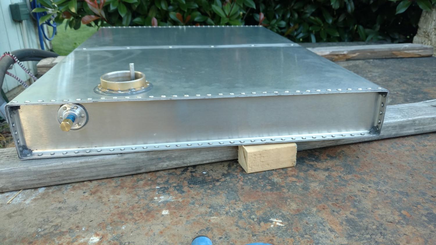
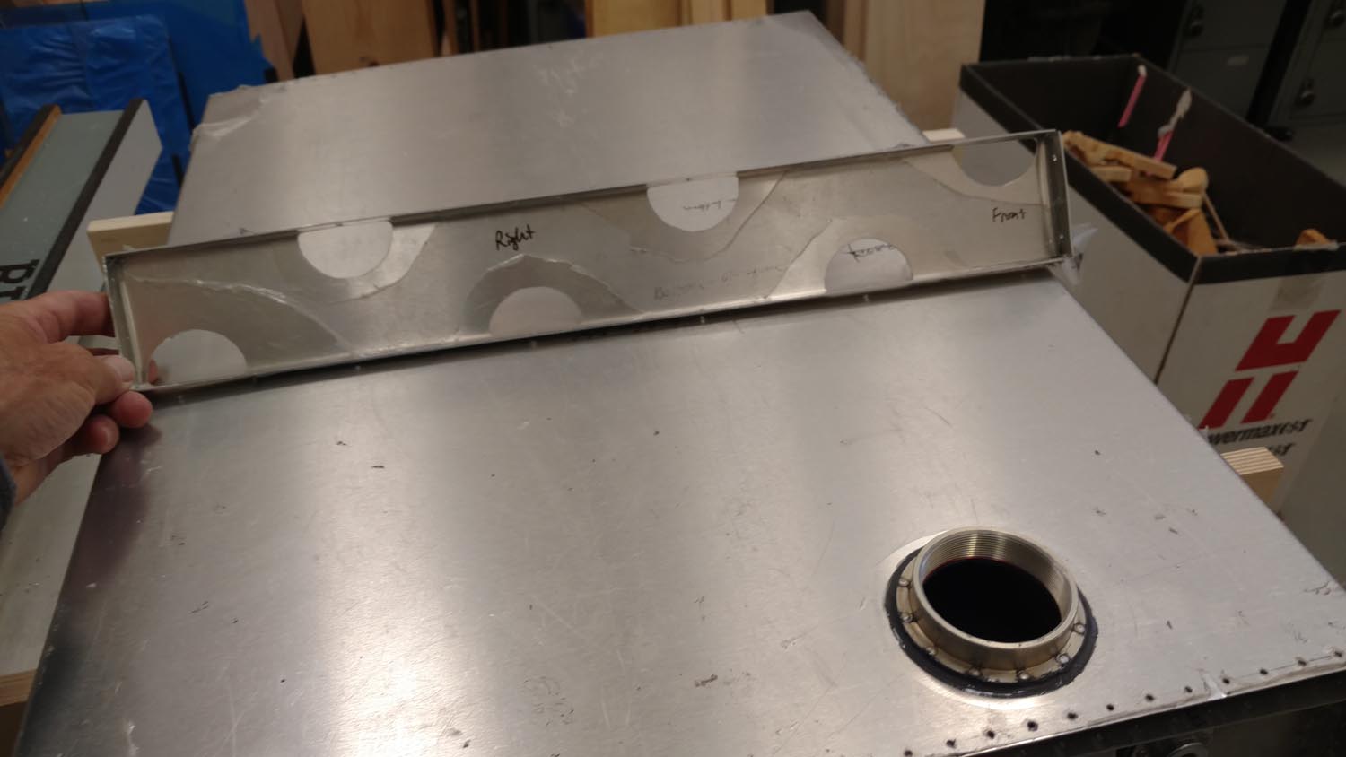
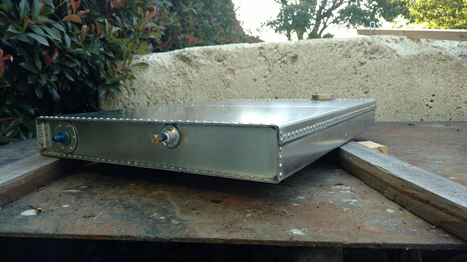
The plan was to bend a single piece of sheet aluminum 4 times to form the main tank body with a single seam across the front. A baffle would then be added in the center to keep fuel from sloshing around excessively and provide support and rigidity. Pieces would also need to be built to go on each end. Careful consideration was made regarding the correct order to make the folds in the large sheet. A mistake here could have made it difficult if not impossible to make the remaining bends because the piece would no longer fit in the bending brake. To increase the volume of the tanks, rather than keep them a perfect rectangular cross section, the front edge was made a bit taller than the back edge.
The baffles and end pieces were cut to size, then the long edges were bent 90 degrees in the brake. A form with a radius along the edge was created out of a piece of hard maple and the remaining bends were accomplished by clamping the sheet against the form and persuading it to bend by striking against a block of maple with a mallet. The corners were drilled with a 1/8″ hole to prevent cracks from developing in the future.
The width of the flanges on the end pieces and baffles were calculated based on the required edge margins for the size of rivets intended to be used. The formula for determining the proper diameter for rivet selection is based on the material thickness.
Rivet Diameter
“A general rule is that the rivet should have a diameter of at least three times the thickness of the thickest sheet that is being joined. For example, two pieces of 0.050 inch sheet are to be riveted together. The proper diameter rivet would be 3 x 0.050=0.150 inch. A 5/32″ (.15625″) rivet would be used.” (atlas-copco.com)
Rivet Length
“The bucked counter head diameter of the rivet joint must be larger than 1.4 times the diameter of the shank according to the military standard. The height must extend to 0.3 times the diameter of the shank. With all mentioned parameters, you can calculate the desired length of the rivet. The allowance is normally about 1.5D.” (atlas-copco.com) The metal thickness is 0.050+0.050=0.10 inch, and 1.5D is 0.234 inch, so the total length would have to be 0.10 + 0.234=0.334 inch for the rivet. Drill some holes in a scrap piece of stock and buck a few rivets for practice. Check the head tolerance to make sure it is satisfactory before moving along to the important project.
Edge Margin
To calculate the edge margin for rivets, use the formula 1.5 x rivet diameter to find where the center of the rivet hole should go. This is a minimum distance in from the edge. It is recommended that you leave extra room inboard of the edge though, if you mess up a hole, you want to still have enough edge margin to install the next bigger size rivet to fix your mistake. Don’t forget to allow enough room inboard of the rivet to provide clearance for the squeezer.
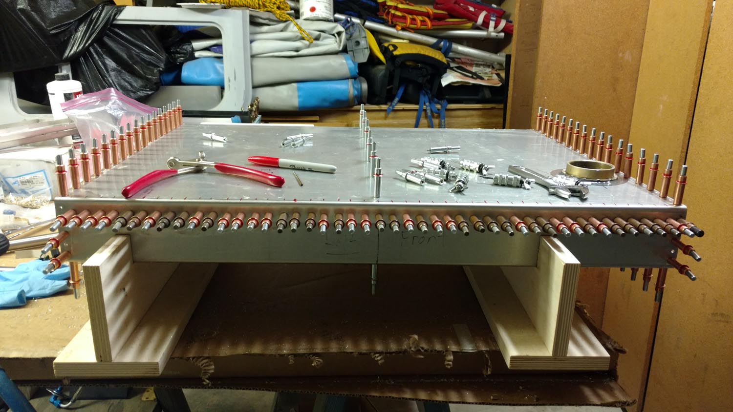
Both ends of the tank would be accessible to use a hand squeezer, but the center baffle would require bucking with a pneumatic rivet gun. Soft rivets are recommended for use when welding tanks as the alloy in hard rivets is not compatible with the welding process. Since these tanks were not being welded, hard AN 470AD universal head rivets were selected. It was very difficult to squeeze these with a hand squeezer. Two pieces of 9/16″ rod were cut to make some handle extensions for the squeezer by sliding them into the handles to provide more leverage.
A friend from the EAA lent me his rivet spacer. This nifty tool helps layout the spacing of all the holes consistently. It can also be used to make the rivet spacing from point A to point B come out evenly. One reference recommended placing the rivets 1/2″ – 3/4″ apart. Another reference recommended spacing based on 6-8 rivet diameters. Stretching the spacer across the rivet line from where the desired first rivet would be, to where the desired last rivet would be, revealed spaces between the holes of just under 1.25″. Since 1.25 divided by 2 is 5/8″, (within the suggested spacing) the rivet line was divided by 2 and the tool was used in two stages to get the spacing to come out evenly across the entire length of the tank.
An EAA member recommended the holes be drilled out with a #33 drill bit, and then be reamed to #30. A reamer produces a much more accurately sized hole than a drill bit. This would give the rivet a precise fit and hopefully prevent the possibility of a leak around a rivet. A jig called a “drill egg” was used to help with getting the holes as perpendicular to the sheet as possible.
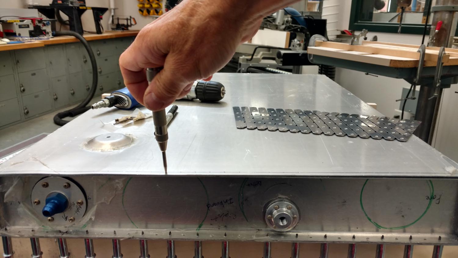
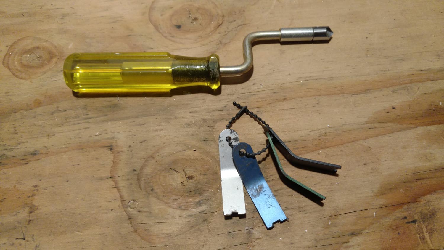
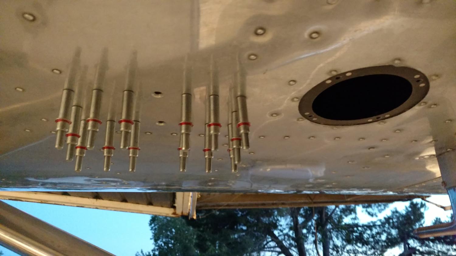
Clecos were used to hold the assembly together as the holes were drilled and reamed. Everything was then disassembled and deburred with the tool shown in the upper portion of the picture below, a very time-consuming task.
Venting
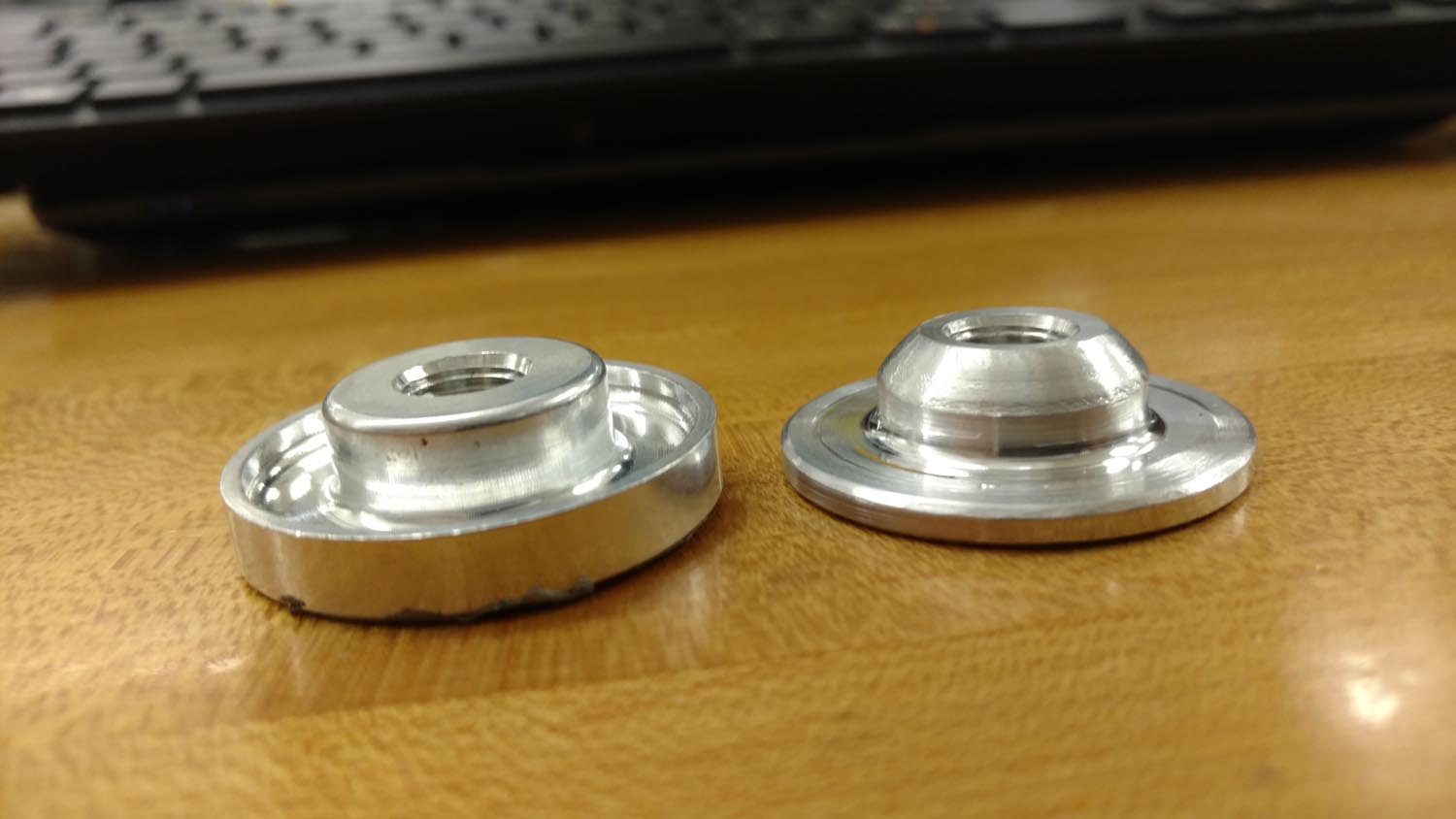
A common problem with the GlaStar fuel venting system is that with full main tanks, every time a turn is made or one wing gets lower than the other while taxiing, fuel comes spilling out of the vent. As others have done to remedy the problem, the vent line from the mains was run into the auxiliary tanks, then a separate vent was run from the auxiliary tank outboard. Aircraft Spruce sells welding flanges in different sizes (example AN867-1) that allow for attaching the vent lines, as well as the outlet/fuel pickup and a drain valve. A 1/4″ aluminum tube inside the tank was bent to terminate up inside the filler neck on one end, and attached to the vent flange at the other. The shape of these flanges didn’t make it easy to use rivets to hold them in place, but with a small modification in a mini wood lathe they were made to work. The edge was chamfered on the ones for the drain valve so they would slip over the hat sections in the wing a little easier during installation.
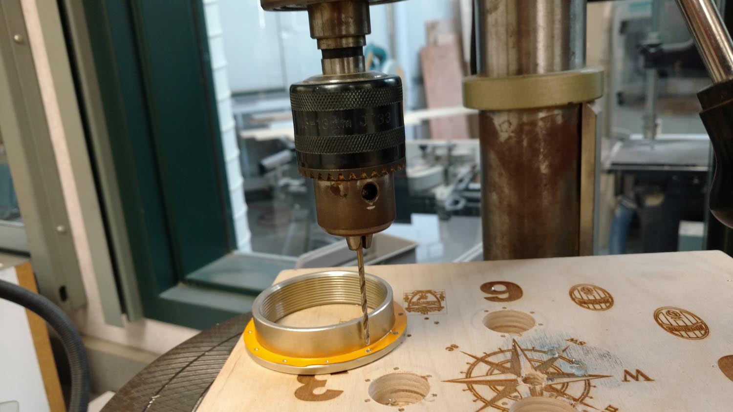
A template for drilling the rivet holes accurately around the edge of the flange was made using the program CorelDraw on a computer. It was then printed with a vinyl cutter actual size, to make a sticker that could be applied to the flange to get the holes drilled evenly. After drilling the holes in the flanges they were placed onto the end pieces of the tank in the desired locations, and the necessary holes drilled and reamed to hold them in place.
Fuel drain
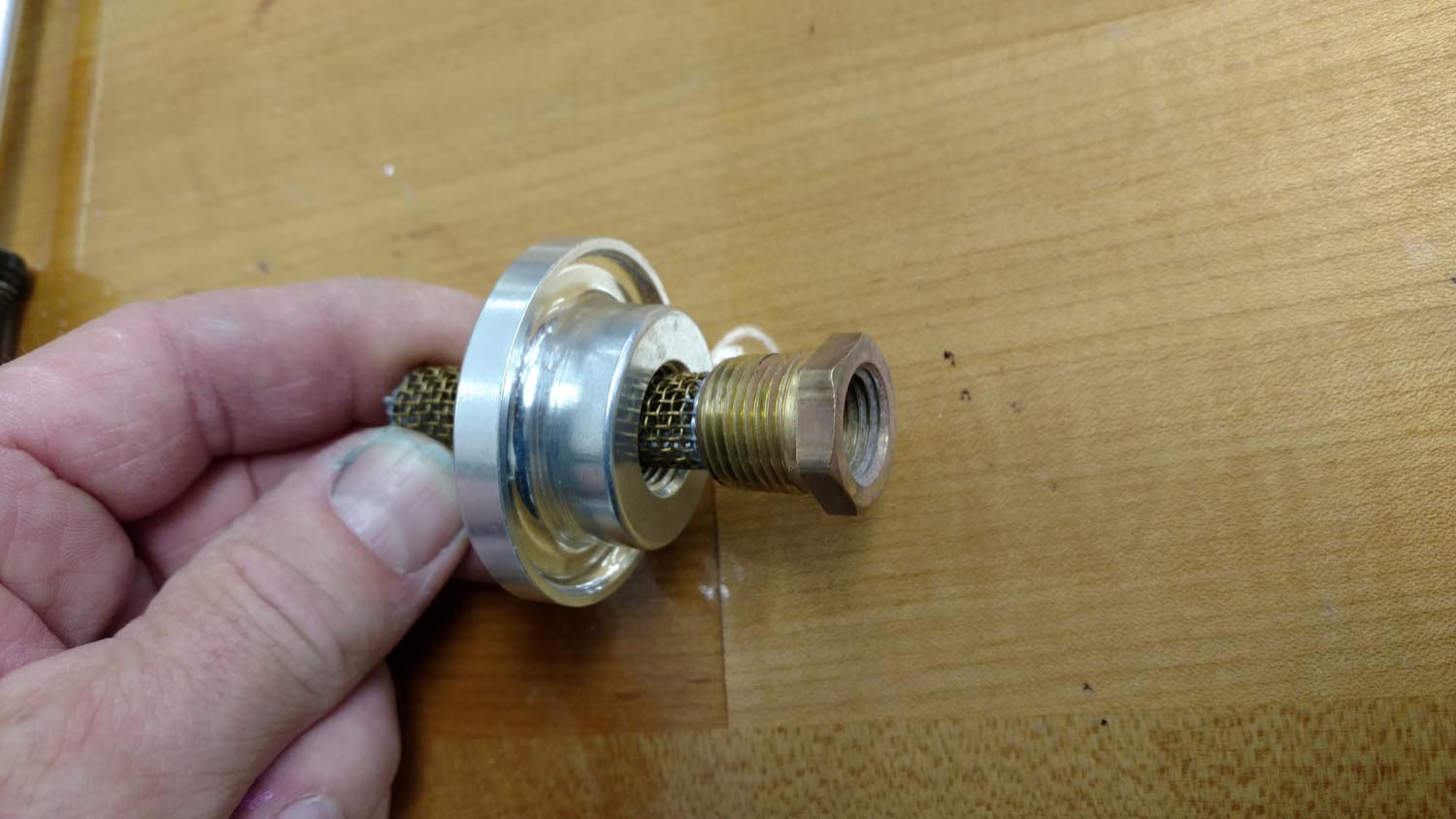
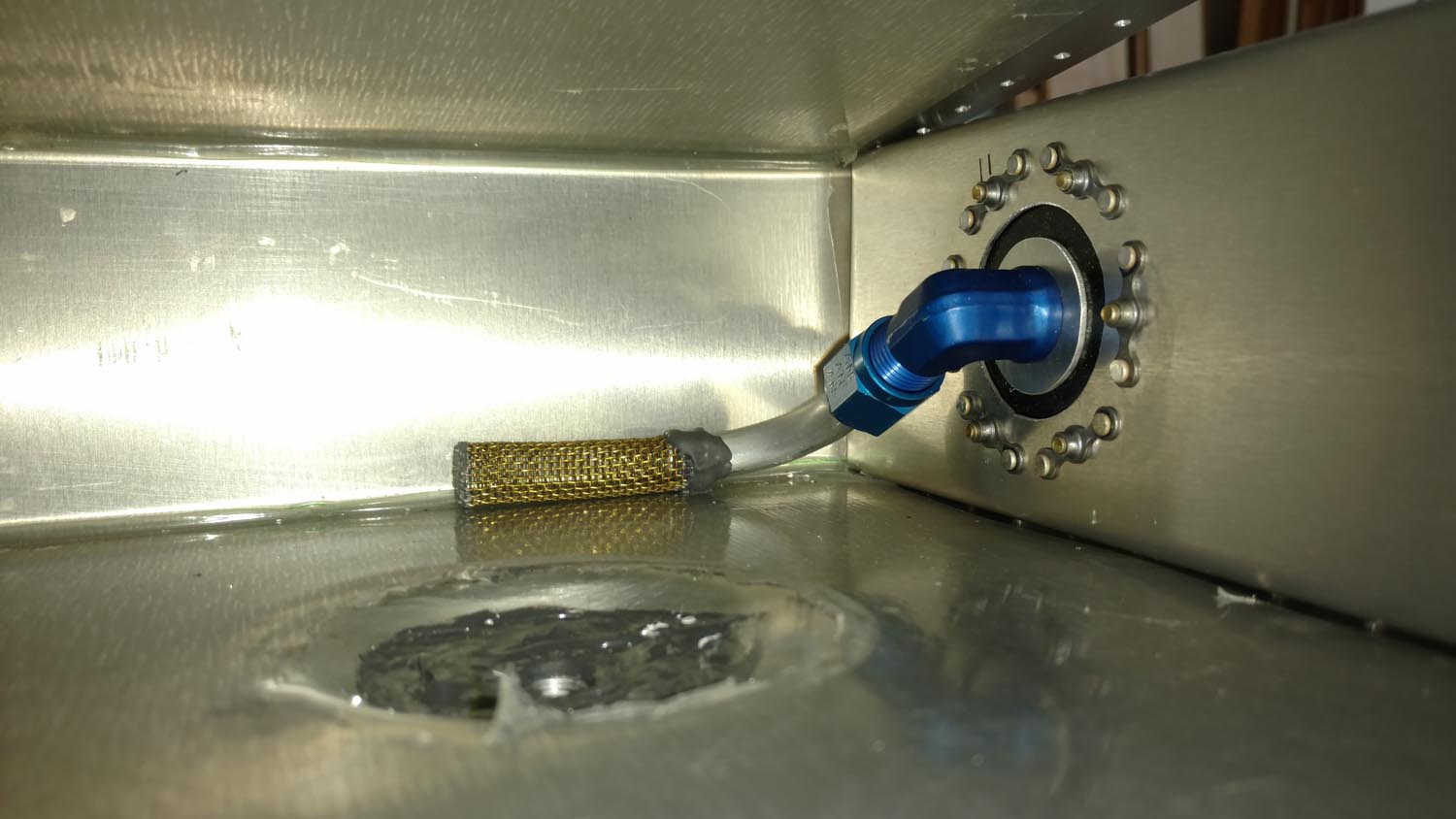
Standard size fuel screens, sometimes called finger strainers (part number 05-17700) were purchased from aircraft spruce (and the 3/8″ threaded flanges that went with them). The problem was the flanges had a 1-7/8″ outside diameter so the screen couldn’t be placed anywhere near the bottom of the tank. This would greatly increase the amount of unusable fuel so an alternative had to be developed. The screens definitely needed to be removable, so the arrangement shown in the second picture below was devised. By removing the screen from the fitting it could be attached directly to a piece of 3/8″ aluminum tubing with pro-seal. Upon testing the tank, it was found that only .4 of a gallons of fuel was unusable in each tank, a very satisfying outcome.
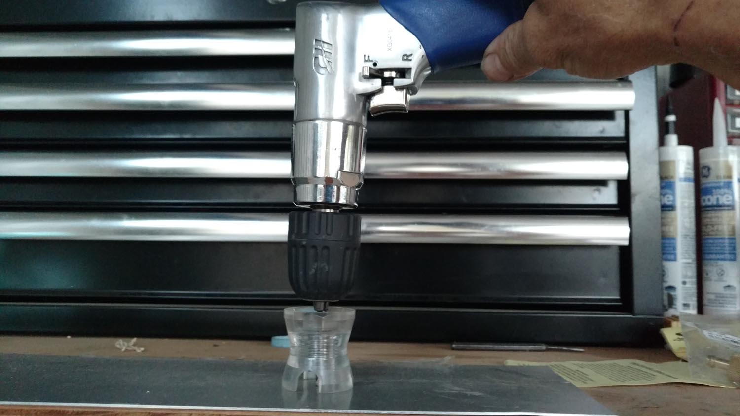
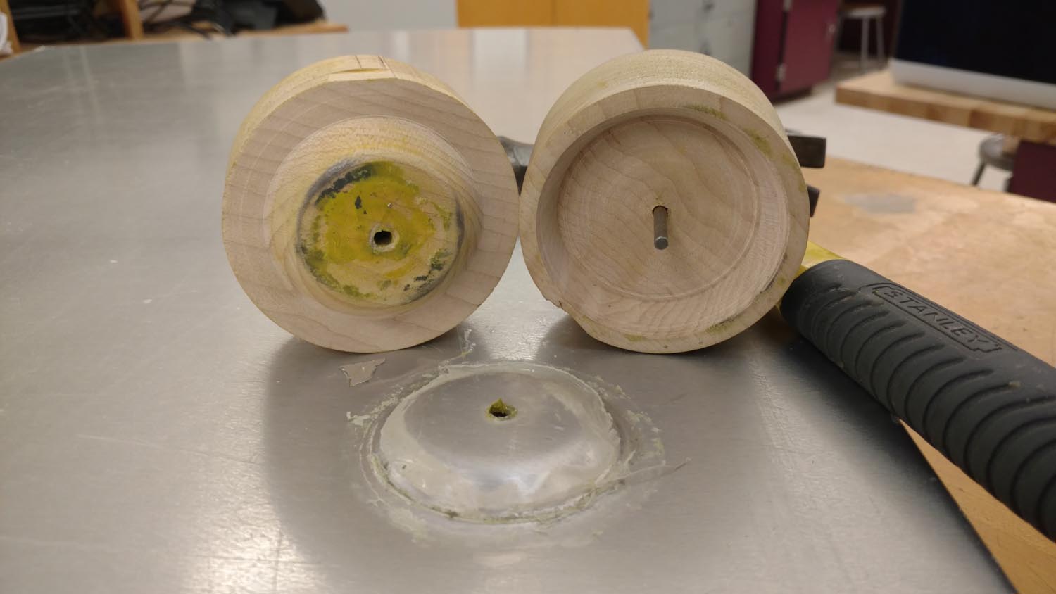
Before assembling the tanks a large dimple needed to be made that would serve as a low point for water to settle where it could then be drained out through a valve and fuel samples easily taken. The mini wood lathe was used again and a male and female die turned that could be squeezed together, deforming the metal to the desired shape. Testing was done on scrap material and modifications made until the correct shape was achieved. The tank was inserted into the wing and careful measuring done to find the desired location for the drain valve. A 1/8″ hole was then drilled up through the wing skin and into the tank. After removing the tank from the wing, this hole in the tank was used to index the center of the die into the correct position, then a hammer was used to force the dies together and create the dimple in the tank. A welding flange with a 1/8″ pipe thread to accept a Saf-Air drain valve (CAV-110 or similar) was then attached with 3/32″ rivets and a layer of pro-seal. Saf-Air drain valves 1250H are highly recommended as they have a nipple so that a hose can easily be attached, and can be positioned to remain open for easy draining of tanks.

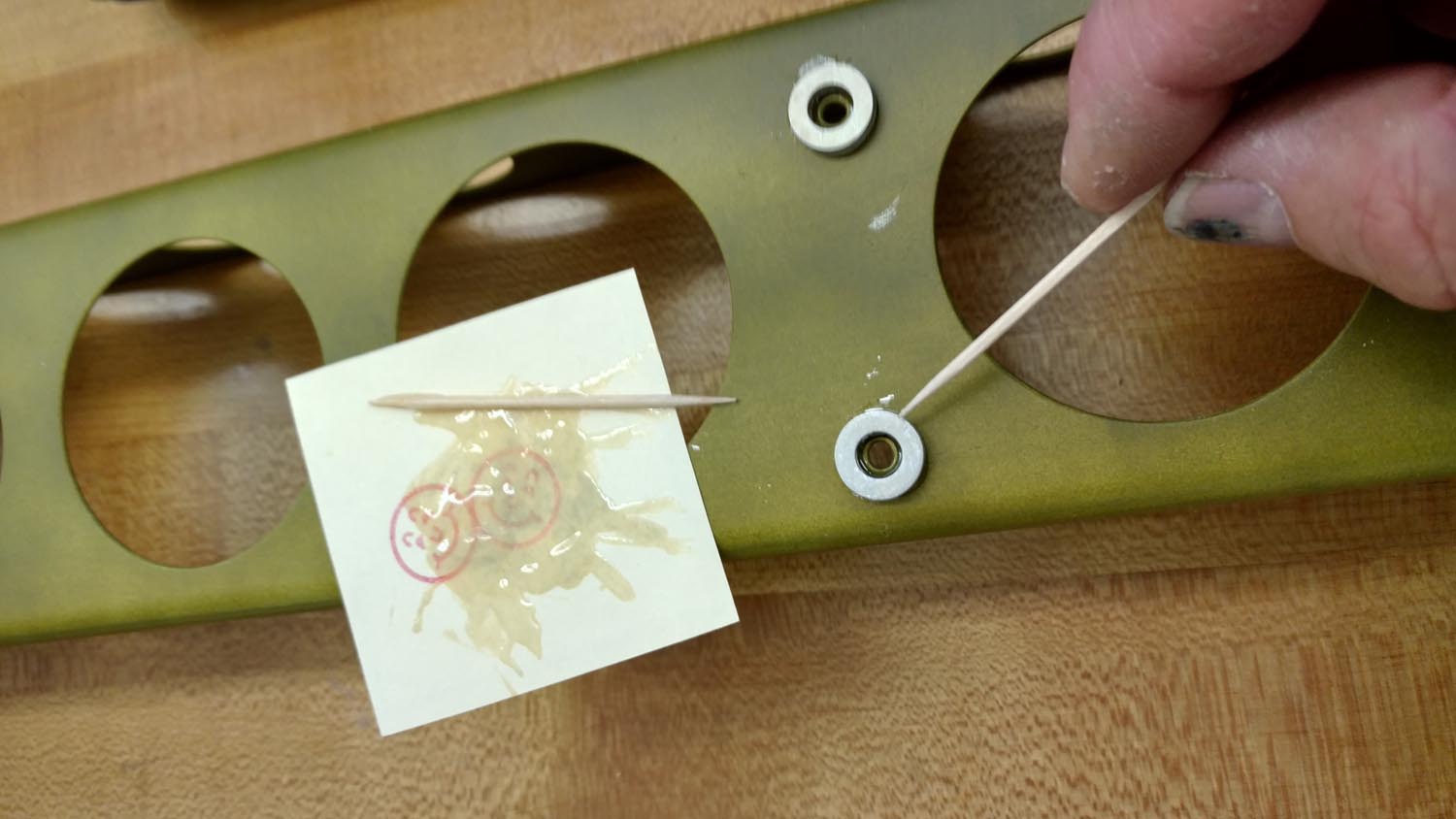
The sticky stuff
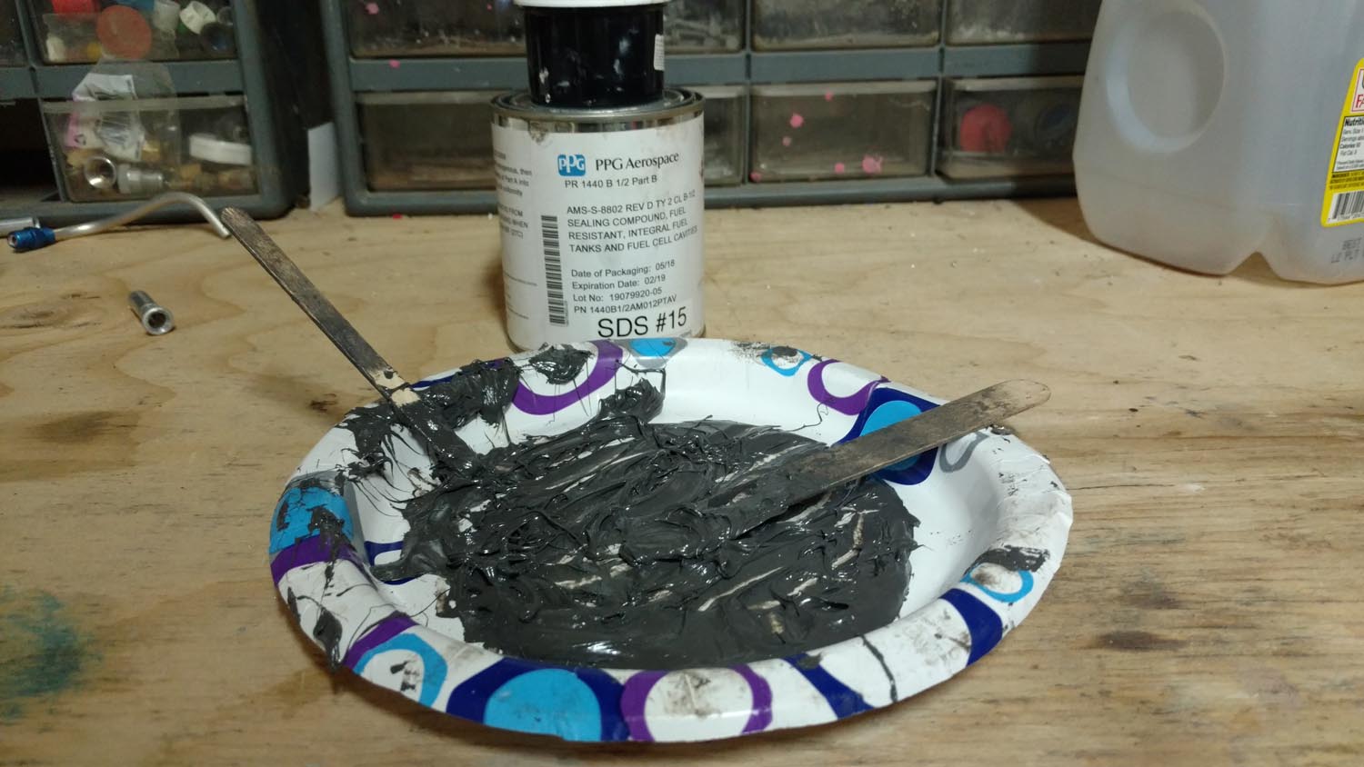
Pro-seal is a 2 part material that is mixed together and remains elastomeric when cured even after prolonged exposure to AVGAS. It is used around seams and rivets to prevent leaks. It is quite expensive ($120 for a pint can). It comes in 30-minute or a two-hour cure varieties, and has shelf life of about 6 months from date of manufacture. The stuff smells nasty and has a way of getting all over everything. Wear old clothes, a respirator, tape long sleeves to gloves, and mask off all areas to avoid making a mess. The stuff doesn’t wipe off easily at all, just smears. Lacquer thinner worked a bit better than acetone for clean-up but still the job was difficult, especially cleaning all those clecos after it began to harden. Paper plates, tongue depressors and popsicle sticks were quite helpful for mixing and spreading the miserable goop which is about the consistency of creamy peanut butter.
Another pilot (professional A&P as well) who drops by my hangar from time to time called me one day and asked if I’d like some pro-seal they were throwing away at work as it was nearing the expiration date. Jumping at the opportunity, it turned out to be the half-hour setting variety. It worked fine for small jobs like attaching threaded flanges, the center baffle, and the front seam, but attaching each of the ends of the tank required the two-hour type.
Filler neck
To determine the location for the filler neck (Aircraft Spruce part # 05-17800) measurements were taken from the fore–aft location of the filler neck on the existing main tank and transferred to the auxiliary location. The inboard/outboard location was determined simply by placing the neck as far outboard as possible, keeping it just slightly inboard of the outboard edge of the tank to allow it to be filled to maximum capacity. A Dremel rotary tool was used to remove the wing skin material, carefully removing just enough and testing the filler neck for fit as the process progressed. Once the neck fit in the hole, the rivet locations were marked through the holes already made in the flange that the filler neck screws into. The tank was then removed, and the holes drilled and reamed. The flange was then attached to the tank with a layer of pro-seal and some 3/32″ rivets.
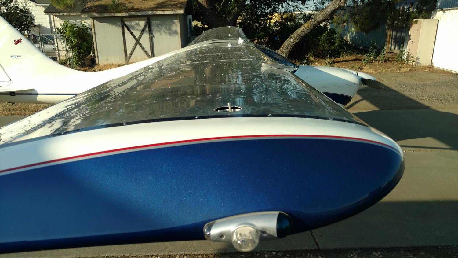
The wing tapers upward fore to aft where the filler neck protrudes. Because the tank is flat across the top, the fuel cap stuck up further above the wing in the front than on the aft side. The look was hideous and added drag. After marking it carefully, a cutoff disc in a Dremel tool was used to slice off the top of the steel filler neck, then remove an additional wedge shaped piece from the lower section. Before grinding or welding the parts were dipped in muriatic acid to remove the cadmium coating which is hazardous. The two halves were then welded together and powder coated.


After completing the tanks, Tom Madden’s method of fuel tank testing was used which was shown in his April 2019 article. A few drops of Gentian Violet antiseptic dye was added to about a quart of acetone, and the mixture shaken to increase the vapor pressure. Luckily there were no leaks! The tanks were then sanded with 320-grit sandpaper and sprayed with a light coat of primer.
Installation
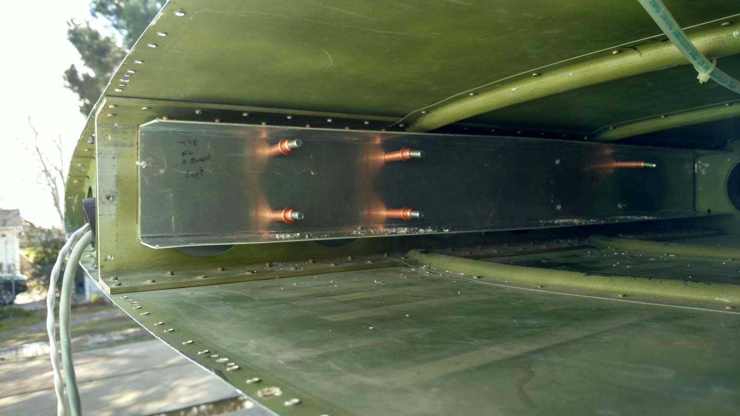
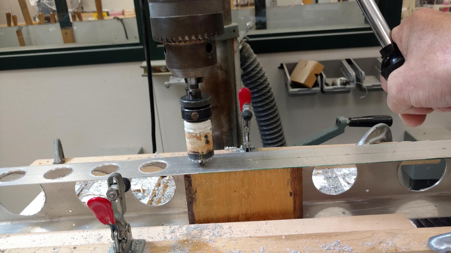
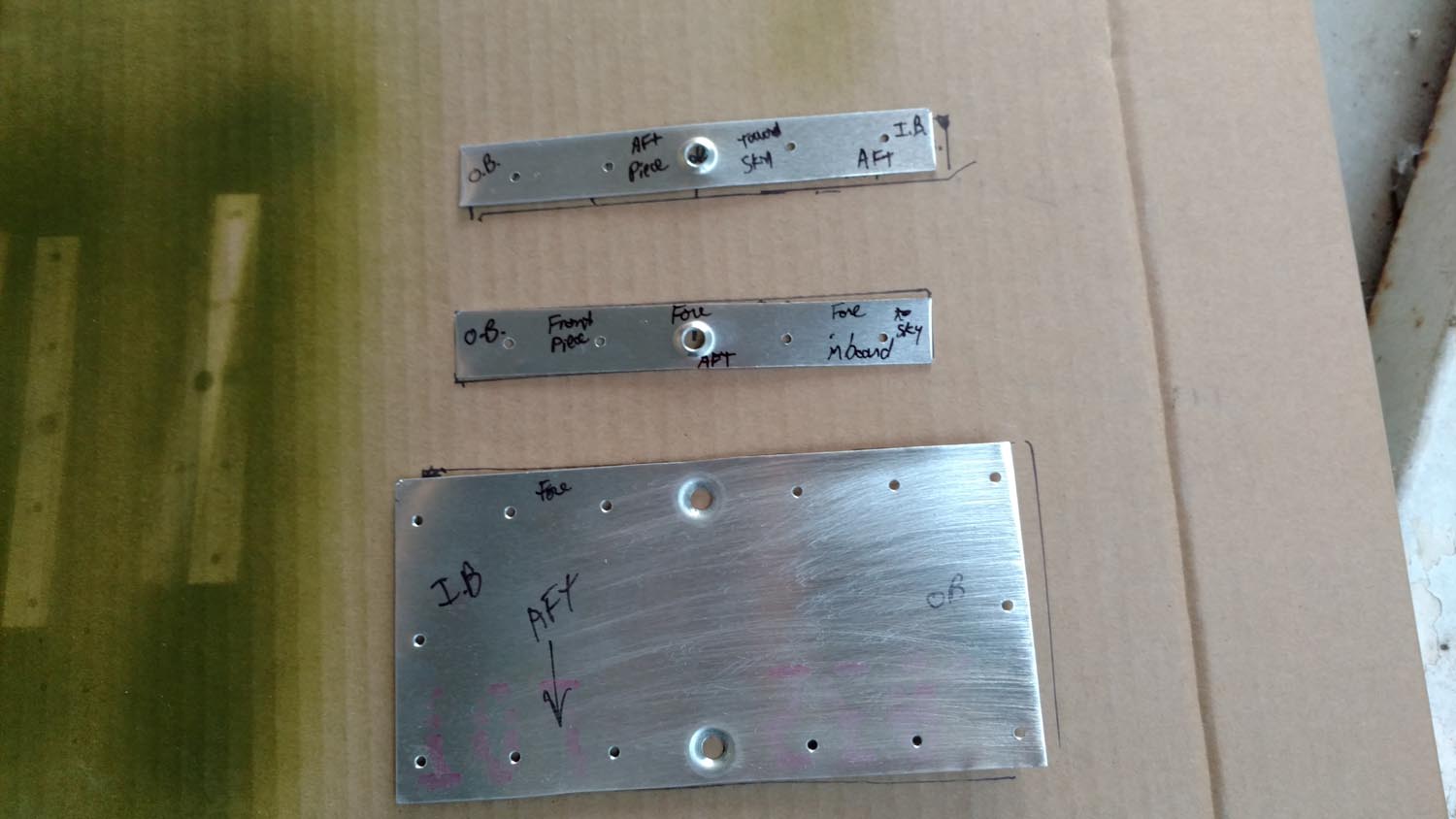
The tanks are cradled in place inside the wing by channels that are mounted to the wing spars. These were made from some scraps left over from the tank material. They look simple enough, but there are over 30 lightening holes that had to be drilled with a hole saw, de-burred, then primer applied. Aluminum washers (1/4″) were placed between the spars and the channels to provide clearance over some universal head rivets that were already protruding from the spars. The channels were then mounted to the spars using CherryMAX flush pull rivets. Rubber spacers were then rubber cemented in place on the inside of the channels to make a firm fit when the tank is slid in place.
A fuel pump must be mounted in each wing that transfers fuel from the auxiliary tanks to the mains. The suggested pumps (Facet 40171) are readily available from Aircraft Spruce. They contain a valve that prevents fuel from flowing in either direction until the pump is turned on. I spent much time researching an alternative pump as the recommended pumps are quite slow. While I found several suitable pumps with significantly higher output, they didn’t provide the necessary valve. My idea was to get an electrically operated solenoid to put in-line that would be activated when the pump was turned on. All this added complexity and weight so the originally suggested pump was used.
To mount the pumps on the wing skin, a doubler was fashioned and installed to provide some rigidity. This was made from .032 scrap aluminum and was integrated into some existing rivet holes in the hat sections after the rivets were removed. Some EAA members have a saying about home building, “You don’t just build one plane, you actually make two.” Getting the layout just right and the edge margins correct took two tries. The decision to dimple the sheet metal for countersunk mounting screws made the installation look a bit more professional.
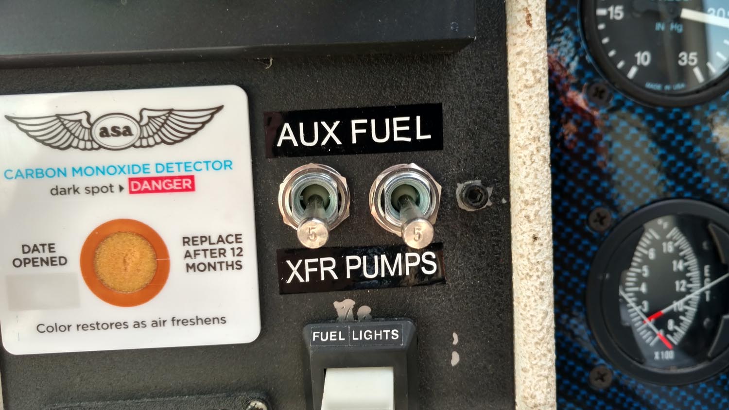
Two 5-Amp switches that double as circuit breakers (Tyco W31X2M1G5) or (A/C Spruce 11-03936) were added to the panel and 16-gauge wires run from the switches up to the pumps.
It was necessary to heat a small nail and carefully pierce the plastic wiring conduit inside the wing near where the pumps were mounted. The pump power supply wire was then fished out through the hole. A task much easier said than done. Waterproof connectors were used to create a removable connection to the pump. The ground wire for the pump was connected directly to the airframe right at the pump mounting screws per the factory installation instructions.
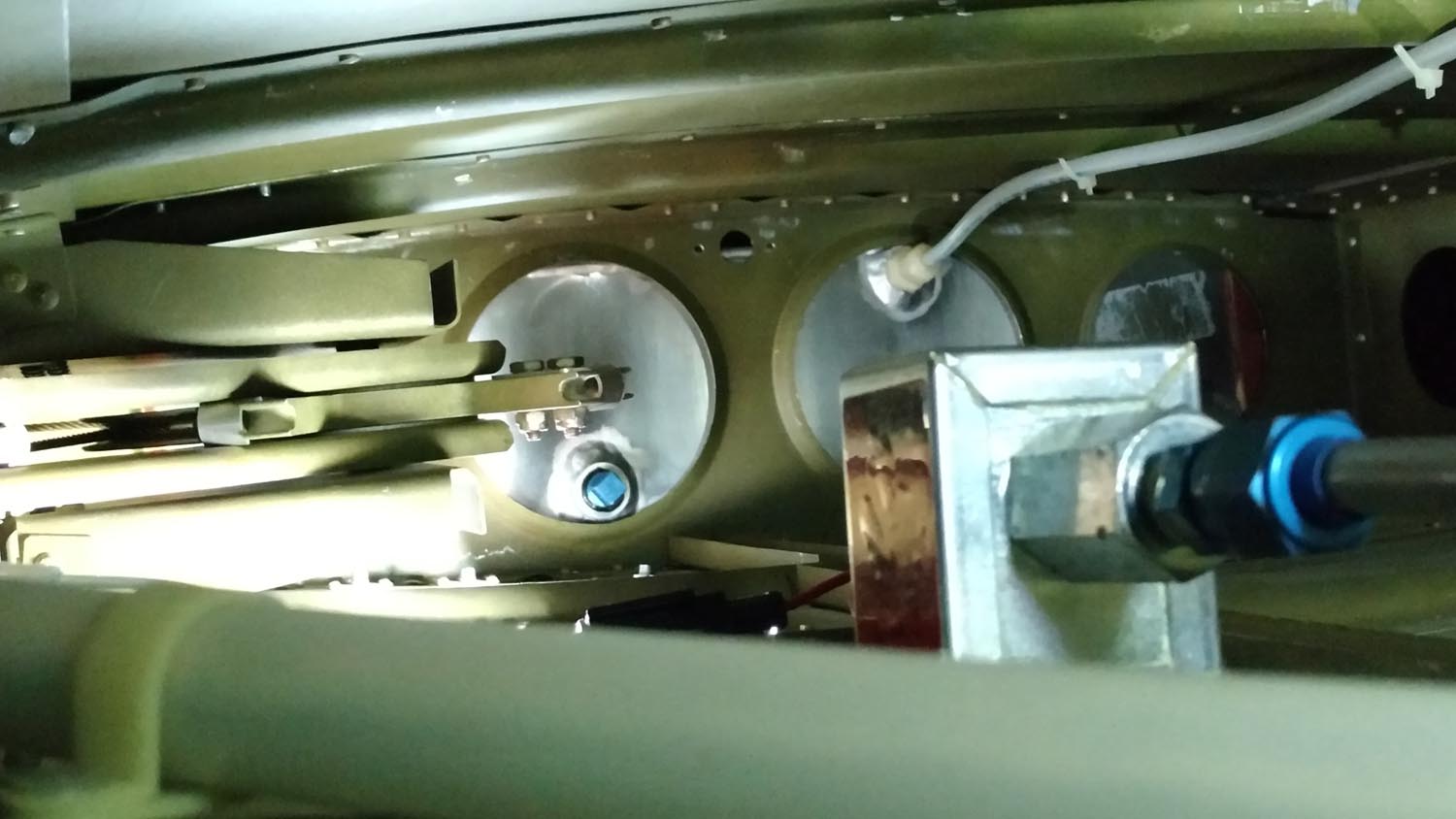
The main tanks had a plug that was removed and 3/8″ fuel line connected there with AN fittings. The other end of the line was connected to the inboard end of the pump. A second line was fashioned that ran from the outboard pump outlet to the new auxiliary tank. These lines were fixed in place with zip ties, stand offs, and supported where possible, but access was quite limited.
To calculate how much liquid a container will hold in gallons, find the total number of cubic inches (length x width x height) and divide it by 231. The calculated volume of these tanks came out to 7.9 gallons, which was verified the first time they were filled at the pump. Maybe this project wasn’t such a good idea after all, it now costs $75 more to fill up! With both auxiliary tanks full my GlaStar can now hold an additional 15.8 gallons of fuel with 15 gallons usable, and that precious fluid won’t be flowing out the vents every time a corner is taken. That adds an additional 2+ hours of flight time at cruise settings with the Lycoming O-320. More importantly they should prove handy for backcountry flying where fuel can be scarce.
On the very first trip with the new tanks a friend was concerned about his available fuel to make it to our next planned stop. We landed at Denio (middle of nowhere) on the Oregon/Nevada border and siphoned a few gallons out of the new GlaStar auxiliary tanks and poured them into his Aerotrek, then both safely continued to our destination.
The completed tanks weighed in at almost 9 pounds each. The two pumps, four mounting channels, switches, wire and fuel lines added up to an additional 6.5 pounds, unusable fuel is 4.8 pounds (but can be easily drained), for an overall total weight gain of 29.3 pounds. It’s amazing how fast extra weight adds up!
A rough estimate reveals close to $1400 was spent on materials and shipping, and another $300 on tools. This is only about a $300 savings from buying the factory built version. But as every homebuilder knows, the lessons learned here are worth more than money. The satisfaction of taking raw materials and creating something usable for the flight of an airplane is priceless. The project took 4 months’ worth of spare time with much of the preliminary research completed before commencing. While the amount of work this project involved was astounding, so is the pride felt in the accomplishment. The experience gained throughout this project has provided the knowledge, skills, and confidence necessary to tackle future sheet metal repairs on this aircraft if they become necessary.
An entire 4′ x 12′ sheet of aluminum was purchased for this project. Hmmm, what can be made now with the remaining 3′ x 4′ piece?


