 Constant-speed propellers and even fixed-pitch units are a significant investment, and often there is a significant lead time between ordering and delivery of the propellers.
Because of these and other reasons, many builders find the propeller arriving very near the end of the project. This is fine but does often lead to a bit of a dilemma for the builder. The work forward of the firewall (engine installation) involves a substantial amount of time installing baffling, induction air kits, fuel lines and much more. However, to complete many of these items, the cowling must be in fitted. So, how do we fit the cowling to the fuselage, since all of S-H’s instructions are based on the concept of blending the forward end of the cowling into an already-installed prop and spinner. Without the prop and spinner it would appear that the cowling cannot be fit, and without the cowling fitted, much firewall forward progress is stopped.
We here at S-H are not are that much different that you builders. For example, our new GlaStar® demonstrator was slated to use the prop off our flying GlaStar® prototype, and we couldn’t have the prop until the very last minute. Needless to say, we have developed some alternative cowling mounting ideas over the years. And besides, it is actually a lot easier to fit the cowling without having to work around the large spinner and the prop blades sticking out.
As background information, S- H has and continues to supply two styles of cowlings, the “long” cowling designed to be used with the extended-hub Hartzell propellers, and the “short” cowling designed to be used with the compact-hub Hartzell propellers. Several different names have been associated with the two types of cowlings over the years— “extended” or “standard” for the long cowling, “non-extended,” “compact-hub” or “aerobatic” for the short cowling—but for the sake of this discussion I will henceforth refer to the two styles as “short” or “long.” The engine mounts for the Glasair kits are designed with a 2° (Glasair I and II) or 1.5° (III) right thrustline offset and a 1° (I and II) or 0° (III) up thrust. The design of the engine mount is such that the rear of the engine is not centered in the engine compartment but the center of the prop will be on the aircraft centerline.
The cowling is merely a fiberglass fairing over the engine. It stretches between the forward end of the fuselage and blends into the propeller spinner at the forward end. The aft end of the cowling matches the fuselage which is complete by this time. This leaves the alignment of the forward end of the cowling and the fore and aft location relative to the fuselage as the fit-up variables.
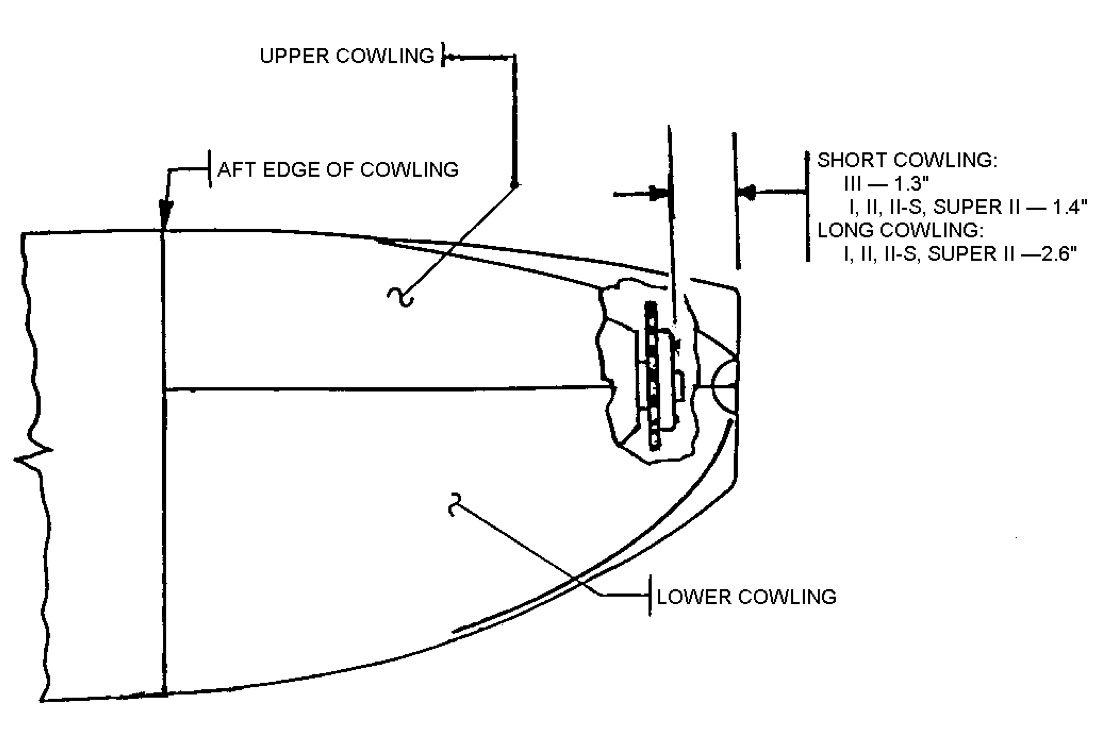
From experience and measuring completed airplanes, the distance between the front of the engine and the front of the cowl is a known (fixed) dimension. Figure 1 shows the dimension for the long and short cowlings relative to what I have found to be an accessible and dependable point on the engine, namely the forward-most edge of the engine starter ring gear. This measurement takes care of the fore and aft cowling variable.
So, the key to fitting the cowling is the positioning and centering of the front of the cowl with the crankshaft flange of the engine. (The crankshaft flange is what the missing prop and spinner will be bolted to). This center- ing is easily done by fabricating a cylinder-like extension on the front of the engine that projects out approximately 8″ from the front of the crankshaft and is secured to the crankshaft. This tool should be fairly solid (since the front of the cowling will temporarily rest on this) and accurately project out the axis of rotation of the crankshaft (since this is what is locating the cowling at the forward end).
After fabricating the crankshaft extension tool, it is time to prepare the cowlings for fitting. The forward ends of the upper and lower cowlings require only a small amount of trimming to allow them to slip together and form what will be a flat-faced circular engine crankshaft opening that will lie directly behind the aft edge of the spinner. Just aft of this flat area and inside of the cooling air inlet scoops two screws will later be installed. At these two points on both sides I like to drill
#30 holes and use clecos as temporary fasteners for the forward end of the upper and lower cowl.
When the forward ends of the upper and lower cowlings have been clecoed together, measure the inside diameter of the circular opening of the forward cowling. It should measure 8″. Fabricate equal thickness of spacer material (I used 5lb. foam and pieces of tongue depressor sticks) and bond them to the exterior of this tool to match the inside diameter of the crankshaft opening on the forward end of the cowl. The spacers should hold the tool centered in the cowling opening.
I have used some old fixed-pitch prop extension hubs that we no longer sell to form the temporary tool. If available, we are willing to loan these out.
Another advantage of using the forward cowl locator tool is that it allows you to fit the upper and lower cowl halves individually. This way, when trimming the aft edge of the cowl halves each side can be done separately, which makes clamping and supporting the cowl for measuring and marking much easier.


