Submitted by Jim Dutton
 During an e-mail discussion about elevator trim systems, with Dick Dobson and Brooks Robinson, Dick mentioned he had installed an electric trim system powered by a linear actuator. Further research into the characteristics of the linear actuator convinced me it was the key component I had been searching for in my quest for an alternative to the factory supplied manual trim system. I wish to thank Allan Cross for his support while developing this article. He rejected my stick figure bellcrank drawing and developed a very nice CAD drawing; he reviewed my rough drafts and helped experiment with resistors and linear actuator voltage reduction.
I designed, assembled and installed electric elevator trim in my Glasair Super II FT using parts from various sources. Standard pulleys, pulley support brackets and springs as specified in the construction manual and supplied with the kit were used. 1/16-inch stainless steel cable and 28-1-C Nicopress sleeves was substituted for the 3/64-inch stainless steel cable hardware. A linear actuator, attached to the elevator trim bellcrank, drives the elevator trim system. The linear actuator DPDT switch was wired with diodes as depicted by the electric flap motor switch wiring diagram.
If the control tunnel was built as specified in the construction manual, there is sufficient space and clearances to house the elevator trim bellcrank and linear actuator. The elevator trim bellcrank and linear actuator are mounted in the control tunnel us- ing AN4-66A bolts. Four pieces of 1/2 inch 40-pound foam, 1-3/8 inches in diameter, were potted into the control tunnel sides, one at each AN4 bolt location. 6061-T6 (3/8 x .058) spacers are installed on the AN4 bolts and AN970-4 washers are in- stalled between the spacers and the control tunnel sides.
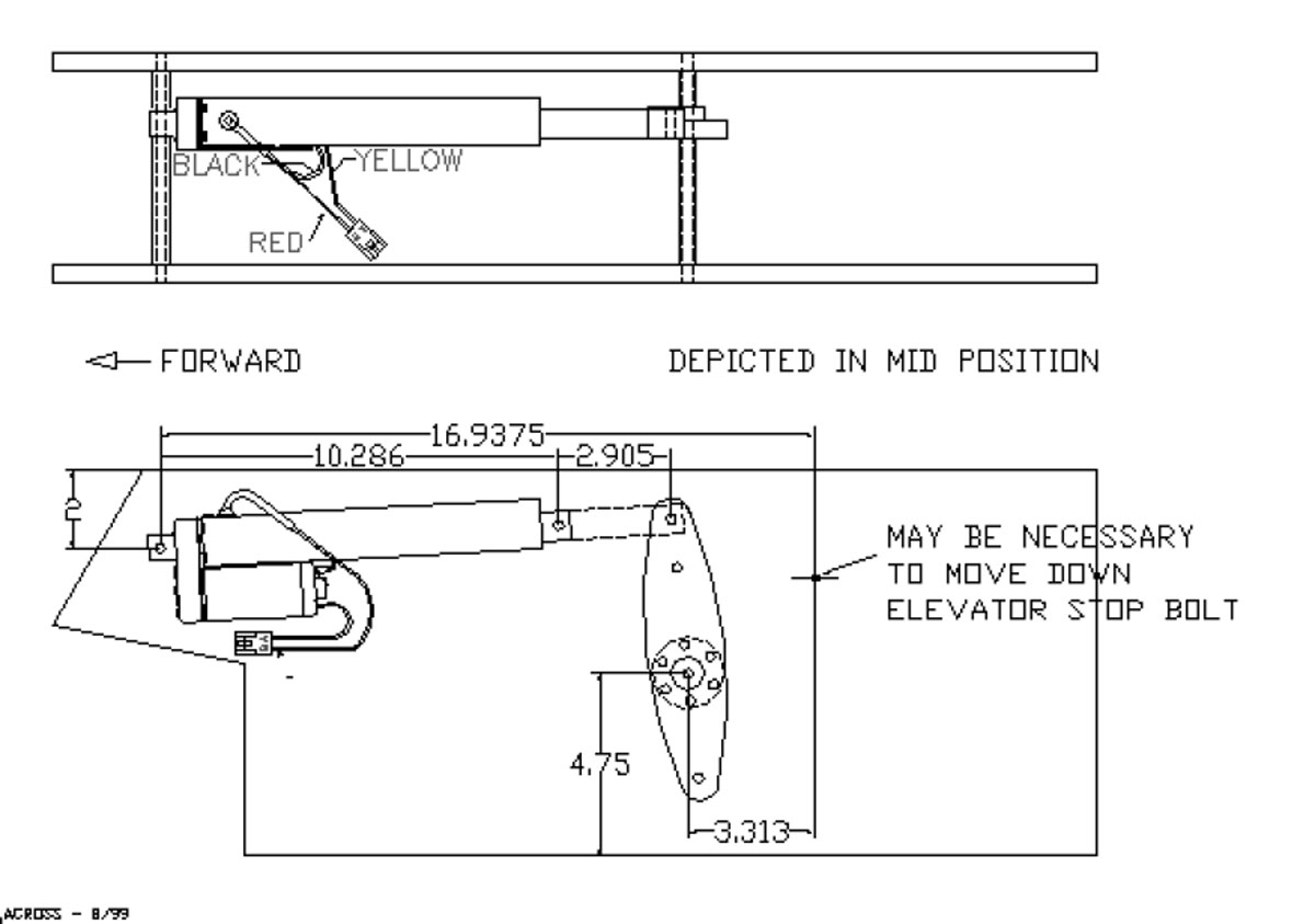
Looking forward, the AN4 bellcrank mounting bolt has a 1 1/4-inch spacer on the right side and a 2-15/16-inch spacer on the left side. The AN4 bellcrank mounting bolt is located 4-3/4 inches above the rear belly pan and 3-5/16 inches forward the AN3 down elevator stop bolt. The AN3 down elevator stop bolt was lowered 1/4-inch to provide elevator trim cable clearance. The AN4 linear actuator mounting bolt has a 13/16-inch spacer on the right side and a 3-5/16-inch spacer on the left side with aluminum washers between the spacers and the mounting boss on the linear actuator. The AN4 linear actuator mounting bolt is located 2 inches below the top surfaces of both control tunnel sides and 16 15/16 inches forward the AN3 down elevator stop bolt.
Cable travel from stop to stop on the manual trim wheel/capstan provided with the Glasair kit measures 4-1/8 inches or 2-1/16 inches each way. Linear actuator travel, limited by internal limit switches, is 5.82 inches or 2-29/32 inches each way if centered. The linear actuator is attached to the bellcrank 4 inches from bellcrank center and trim cables are attached 2 3/4 inches from bellcrank center. Elevator trim bellcrank design presents the builder with many options concerning shape, size, material and associated hardware. 1/16-inch 2024-T3 was used for the bellcrank plus bearings and steel bushings were installed to reduce wear. The bellcrank is 1/2-inch-thick (8 layers 1/16-inch 2024-T3), 2 inches wide in the center and 7-7/8 inches long. Six inner layers of 2024-T3, 4-7/8 inches long, are contoured on one side to provide rod end bearing clearance throughout full range of travel. Two middle layers of 2024-T3 are relieved to accommodate the BC4W10 bellcrank bearing.
Heim HF-3 rod end bearings and AN170-16RS cable eyes are used to attach the elevator trim cables to the bellcrank. An AN4 bolt, inserted through steel bushings in the bellcrank sides, attaches the linear actuator to the bellcrank. The bellcrank is 1/2-inch-thick and the linear actuator shaft is 3/4-inch diameter. A piece of 1/16-inch 2024-T3 was bent, 1-3/4 inches and 2-1/4 inches from the end, to create a 3/8 inch offset and riveted to one side of the bellcrank to compensate for this difference. That side of the bellcrank was shortened 1-1/8 inches to provide clearance for the linear actuator shaft.
According to manufacturer’s specifications, linear actuator travel may be slowed by reducing voltage up to 50 percent with no degradation in performance characteristics. At 12 volts, actuator travel is approximately 1 inch per second. Travel time was increased to approximately 1.66 seconds per inch travel using 1.65 Ohms resistance. Two 25 watt 3.3 Ohm resistors, in parallel, were used to reduce the voltage to 9.08 volts and allow a maxi- mum current of 5.50 amps. This may be slow enough to reduce sensitivity when making minor trim changes. Flight tests are required to deter- mine if further adjustment is necessary.
The following list contains items purchased for this project. Miscellaneous items from my shop aren’t listed, such as, 1/16 inch 2024-T3, rivets, electrical wiring materials and various AN3/AN4 bolts, nuts and washers.
(1) Warner Electric Linear Actuator S12-17A8-06 – $161.00
(1) DPDT Rocker Switch – $9.95
(4) Diodes – $7.00
(2) Bolts AN4-66A – $18.40
(1ft) 6061-T6 Spacer Stock 3/8 x .058 – $0.89
(1) Bellcrank Bearing BC4W10 – $16.85 (20ft) Control Cable 1/16 7×7 SS – $5.00
(8) SS Cable Thimbles AN100C-3 – $1.20
(16) Nicopress Zinc Sleeves 28-1-C – $2.24
(2) Heim Rod End Bearings HF-3 – $13.90
(2) Cable Eyes AN170-16RS – $10.20
Total Cost: $246.63


