Submitted by By Tom. M. Taylor, Aeropride Technology
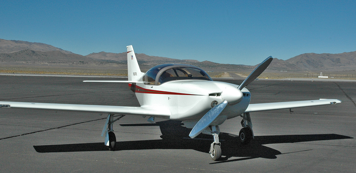 N24TX is an early Glasair IIS-RG with a 200 hp Lycoming IO-360-C1C. I had heard that the larger engine was presenting cooling problems in G-Is and IIs, so I decided to face into this problem early on, reduce drag, and to maximize normally aspirated manifold pressure in order to “have the best of all worlds” for my intended mission.
The current configuration includes improvements made to the given design during construction and has evolved through many hours of modification and flight testing. To put oil cooling problems aside, I installed a G-III cooler with efficient air flow through it. The weight penalty is maybe a pound and that problem was solved.
On a Southern California hot day I typically see a maximum temperature of about 215 deg. during a 120 kt. climb to 8500 ft. or so, followed by cooling to 190 deg. (Vernatherm opening/closing) for cruise. The 225 deg. maximum I’ve ever seen was on a steep climb out of Parker, AZ with a 115 deg. OAT with minimum cowl inlet sizes of about 14 sq. in. each. For cooling drag reduction and efficient air cooling of the engine I followed the rules for a good venturi design.
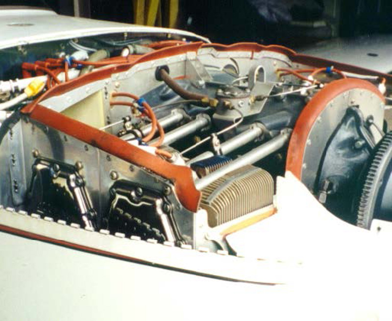
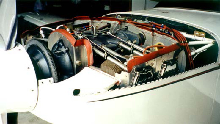
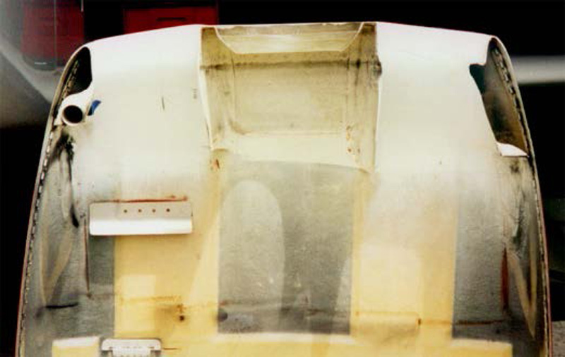
The engine baffling seals to the top cowling to form a pressure chamber. All cooling air is forced through the cylinder/ head fins and the oil cooler (in this case a Glasair III Cooler and baffle inlet assembly). All air exits forward of the rear baffling which is sealed at the side of the upper and lower cowl sides. This aft baffling continues down the back side of the engine and angles along the lower motor mount tubing to the bottom of the firewall/lower fuselage flange. This channels the exit flow and forms a volume behind the engine (accessories, etc.) that remains just above ambient temperature.
 The entry of all inlets should be a clean airfoil shape and the down stream walls should not diverge more than seven degrees in effect. That is, the sectional shape of an interior surface would look like a wings upper surface for straight flow. The airflow may be turned as long as the opposing wall doesn’t allow more than the ideal downstream expansion rate (seven degrees).
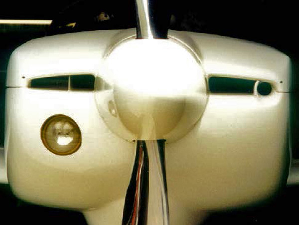
The cross-sectional shape should be circular but can transition to a rectangular shape of a large plenum chamber. I wanted to keep the ”Glasair look”, so the efficiency is slightly compromised here. It’s important to keep all leaks to a minimum. After making only small gains in manifold pressure by modifying the NACA inlet, I switched to a ”ram air” design. The N24TX engine/servo inlet expansion ratio is 2:1. 2:7 should be the minimum if length is a restriction.
The throat diameter is 1.6 in. I used a standardized formula (see your friendly F-l builder, bigger isn’t always better) to determine this size as a compromise to many factors. It’s important not to place the engine/servo inlet near the spinner. The boundary layer is too thick and the propeller blade base area causes undesirable vortices. There actually may be some gain from propeller pulsations with an outboard and properly phased location. LoPresti thinks so anyway.
Next project, to improve the outlet side of the equation.
N24TX measured performance
R.A.C.E. Fall Kilo Trials, november 1996: 261.2 mph
Cruise – Arlington, WA (KAWO)-Pacoima, CA (KWHP) 7/14/1996 non-stop, 1035mi, mostly 9500’, 11,500’ over the Siskiyou mountains, winds light & variable
Full throttle – 2400 rpm (normal cruise setting) time enroute: 4:45
Fuel burn: 42 gal (8.8 gph, 24.6 mpg)
Fuel remaining: 19 gal (2.1h, 458 mi)
Average speed: 218 mph


Hello, I am a new Glasair IIs owner with angle valve 200 hp engine (N63DK) with oil cooling questions:
1: does anyone recommend a larger oil cooler? if so, which one?
2: Is there a better oil to use to reduce heat or oil breakdown?
Thank you
Torsten
Hello, Can anyone provide me with a source where I may purchase resin and bi-directional cloth for my Glasair II project. Thank you.