 Submitted by Carter Boswell
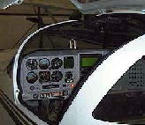
The multicolor rectangle thing on the glare shield is my AOA indicator in the “up” position. When retracted it sits flush with the top of the glare shield out of the way and this is the normal position when I’m flying. I would have mounted it on the left side of the glare shield (à la U.S. Navy, like the AOA indicator used by carrier pilots), but space above and beneath the glare shield did not allow for this.
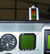
The unit is always powered up whenever my master switch is on. It goes through a 10 sec. built in test then is ready to go. Notice the round tab on top of the Bezel. When in the flush/down position I pull it up to the vertical using this tab so that it’s in its upright and locked position. It’s held upright by the friction between the hinge pin and the hinge. No fancy mechanism to hold it up. I used a center punch to flatten the hinge against the pin. Works great so far and the price is right. The hinge weighs just a few ounces so there really is no need to build something that locks it into place when either down or up. The bezel is just aluminum sheet with four holes drilled in it to accommodate the mounting screws that come with the AOA kit. I welded the tab on the end to make it easy to lift up and down.
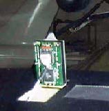
Note the circuit board on the back of the AOA unit, and the Power/info line coming up to the five pin connector on the circuit board. When maintenance is necessary under the glare shield the connector is easily disconnected by pulling down on the connector pin. Takes about a second. The compass above the AOA indicator is not affected by the AOA electric field.
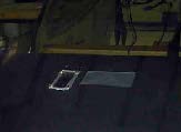
The bezel tab keeps it from falling through the glare shield. Two cleco holes in the glare shield indicate how I kept the hinge tab steady when I potted in the hinge tab with mill fiber.
Underside of right wing tip looking up from beneath the wing. Lots of stuff here.
A. Cav 110 drain for wing tip fuel tank
B. Main wing fuel and wing tip tank fuel vent
C. AOA hole
D. Cav 110 drain for AOA unit if water goes into hole on top of wing
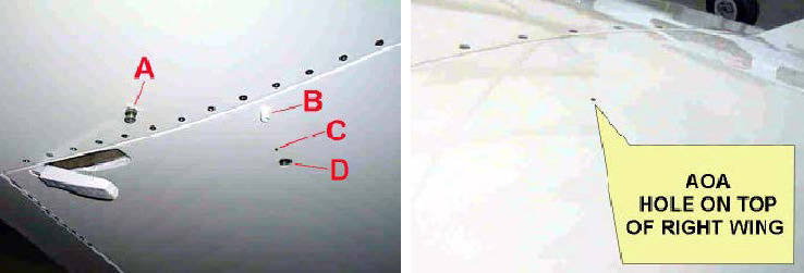 Located about 3” inboard of my wing tip attach joggle is the AOA hole located on top of the right wing. (cover this before you wash your plane) I didn’t look up the drill bit I used but the hole is very small about 1/8th of an inch. I have yet to paint on the placard that goes around the hole. The kit maker supplies a little stencil with which to mark the upper wing hole with a placard.


