Cliff Faber shares some hints and tricks for the installation of S-H’s popular fuel vent float valve installation in Glasair I and II aircraft. Although this option was designed for later Glasair models, it can be installed quite easily in early Glasairs and offers the same considerable benefits to pilots of the “oldies but goodies.”
The wing tank design in the Glasair aircraft is the ultimate in simplicity with its single leading-edge fuel tank. This system allows for maximum capacity, while simplifying fuel management by allowing the pilot to operate the airplane using only the “main tank” fuel selector position.
As with all systems, however, there is a compromise inherent in this fuel system design. The outboard fuel tank vent lines have very little room to rise prior to exiting the aircraft. With the long, low-dihedral wing, and a full fuel level in the wing tanks, a small increase in the elevation of one wing tip relative to the other, such as might occur when the aircraft is parked on an incline, can result in fuel flowing overboard through the “low” wing-tip vent line. S-H and its customers have tested several wing-tip vent combinations over the years, all of which also had some drawbacks, such as low points.
The introduction a couple of years ago of the fuel vent float valve (FVFV) option has proven to be a very effective solution to the fuel venting situation for many builders and pilots. Unfortunately the original design and installation instructions were tailored to the wing tank design of the Glasair II-S, Super II and III models. Glasair I and II builders, as well as people fabricating tank systems of their own design, found it difficult to install these units in their wings.
The FVFV has a mounting plate with two protruding tubes designed to enter the outboard end of the wing fuel cell. This is straightforward enough on the aircraft with the fuel cell ending right at the wing tip, but it is awkward to install on wings where the end of the fuel cell is approximately 18″ from the tip, as it is in the Glasair I and II. With the fuel tank end rib in this position, the standard option was to cut an access hole in the lower wing skin just outboard of the tank end rib and try to install the FVFV through this opening.
After studying this situation and helping customers devise methods for utilizing this valve in their systems I have come up with some ideas I’d like to share with builders who have not yet installed FVFVs because they thought they wouldn’t work in their airplanes. These methods allow the FVFV to be “remotely mounted” on the outboard wing rib even though the tank ends further inboard. Thus, no holes need to be cut in the wing skins, and access to the FVFV remains a simple matter of removing the wingtip, just as it is in the later Glasair models.
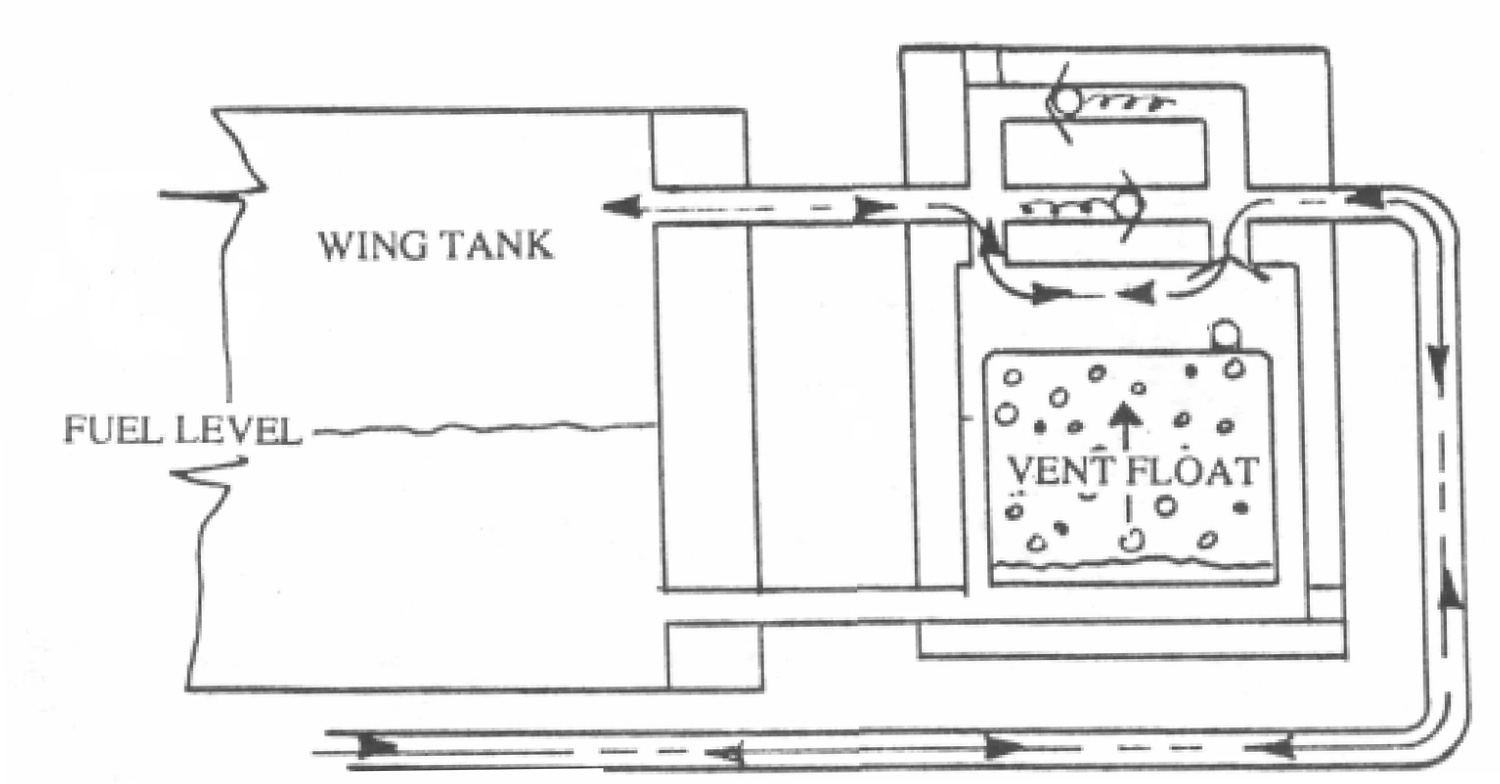
To function correctly, the FVFV requires two lines into the outboard end of the wing fuel cell: a “vent line” going to the highest point in the outboard end of the cell, and a “drain line” going to the bottom of the outboard end of the cell. This dual-line system provides a “loop” type system, allowing the float in the FVFV to move upward as the fuel level in the tank rises. As the fuel level nears the top of the tank, the float closes an exit port to the overboard vent line, preventing fuel from venting overboard.
The upper vent line is in place in most aircraft already, and in most cases it can be connected to the FVFV using techniques that I’ll describe below. The installation of the lower drain line is the most difficult aspect of the remote mounting of the FVFV
The valve can be remotely mounted (relative to the end of the fuel tank) and connected into the existing vent line by installing different AN fittings in existing ports in the FVFV body and fabricating and installing a new drain line. We need not always use the mounting plate to provide access to the end of the fuel cell. Using a 1/8″ NPT pipe thread tap to cut thread holes, we can modify the existing ports on the FVFV to accommodate AN fuel fittings. The mounting plate can be replaced by a close-out plate fabricated from either .100″ thick aluminum sheet or angle stock. This new plate should be threaded to allow the AN509-6R32 screws provided with the FVFV installation kit to be used to attach the FVFV to the plate. The O-rings provided in the kit (P/N 620-0568-110) can be used to seal the mounting plate ports when the new plate is installed.
The first models of the Glasair I and II series used a vent line at the outboard end of the wing, which extended to the wing tip. This line can be used to connect the vent line to the FVFV, using either an AN816-4D nipple (when 1/4″ vent lines are installed, as in Glasair I aircraft) or an AN816-6D nipple when 3/8″ vent lines are installed (such as in Glasair II aircraft).
The new drain line can be installed using some simple “custom” tools. First (if necessary), cut a large access opening in the outboard leading edge rib to access the dry bay outboard of the fuel cell. Working through this rib opening, use a 3′-long section of 3/8″ diameter aluminum tubing with one end sharpened with a file to make numerous teeth, to cut a 3/8″ diameter circular opening in the lower, aft corner of the fuel cell. Use a vacuum while drilling to minimize dust entering fuel cell. It may be necessary to use a rat tail file to slightly enlarge the hole enough to allow the new vent line to be inserted.
Then use a 90° hook on the end of a long shaft to remove the foam core around the new hole. Once again remove the dust and chips using a vacuum. Drill a resin-injection hole in the upper end of the foam-cleared area to allow resin to be inserted into the cavity around the inserted drain line, thus sealing it in place. The access hole in the rib will allow you room to reach in with a syringe filled with resin/Cabosil mixture to fill the cavity around the drain line. Additional fill material can be packed around the outboard face of the fuel bay end rib and the drain line to provide additional sealing. Be sure to rough up the aluminum tube to ensure a good bonding surface.
The existing fuel vent lines should be modified as necessary to compensate for the size of the FVFV. Support the installed FVFV in the wing tip by filling above and below with RTV silicone sealer. The clearance is relatively close, so this method provides ample security for the unit.


