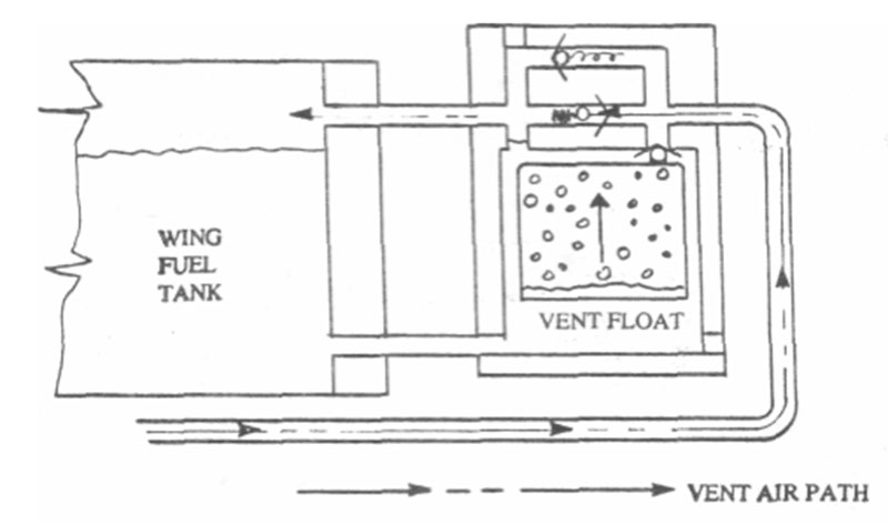
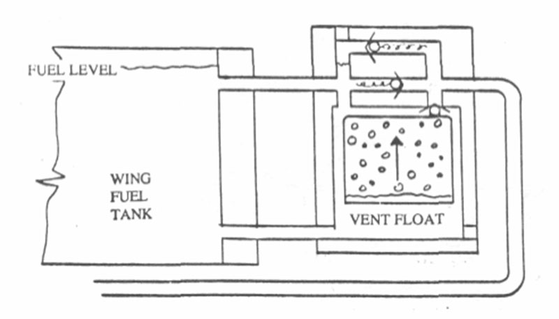
We felt that the following schematic of the FVFVs would help to better understand their function. Though Glasairs have been operating successfully for 15 years without them, they are a real convenience to have and can prevent embarrassing, not to mention hazardous fuel spills if the proper precautions are not taken.
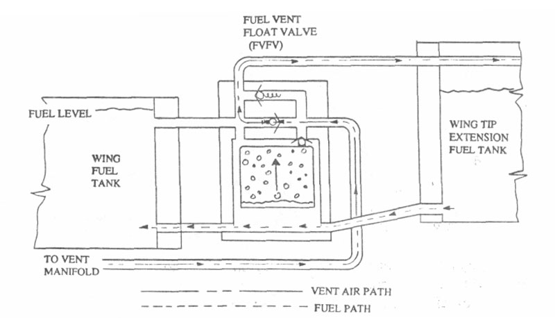
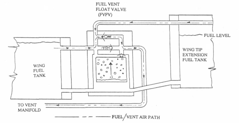
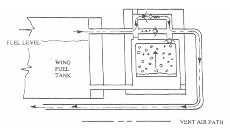
The fuel vent float valve option (332-0490-501) is designed to be installed on the outboard face of the “I” rib, forward of the main spar shearweb, however can also be installed remotely for installations where the standard installation is not possible. An internal inverted cup acts as a float to rise as fuel enters the valve body through a 3/8 inch tube located at its base. As the float rises with the fuel level, it seals off the fuel vent to prevent fuel from spilling overboard. Should there be fuel expansion due to a temperature change, a pressure relief valve will open to relieve excess pressure in the fuel tank. If the valve should freeze up from cold temperatures or stay closed in any way, such as when wing tip extension fuel tanks are used and the tanks are completely full, there is also a check valve that will open to allow the engine to pull fuel from the tank by letting air flow into the tank. Both check valves are located in the upper housing of the FVFV. However, with most standard installations the main tank is also vented to the header tank which is vented overboard and both of these check valve feature will not be activated.
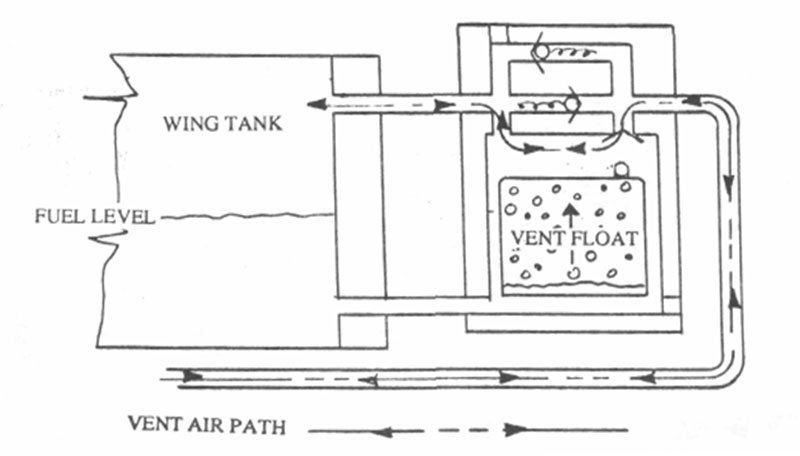
An additional feature designed into the float, utilizes the valve as an acrobatic valve for inverted flight. The inverted cup design traps air inside to act as a float. When flying upside down the cup fills with fuel and the weight of the fuel closes the valve to prevent the fuel from spilling out the vents.
To install the float valves in conjunction with the Vision Microsystems fuel probes, the fuel probes should be located about 4.5 inches forward of the main spar shearweb to allow space for mounting the valves. However the valves can be installed with the fuel probes as little as 2-1/8 inches forward of the main spar shearweb, if the wing tip extension fuel system is not used. We modified the upper forward port on our FVFVs to clear the fuel probe for retrofitting to our Super II-S demonstrator and were able to actually install them with the wing tip extension fuel system and the 2-1/8″ dimension.