I have, I think, found a better way to fabricate the header tank and rudder supports than the method outlined in the builder’s manual—it involves building up the structures on a workbench, then final fitting and bonding in place.
This eliminates all the back strain associated with bending over the forward part of the fuselage and much of the work with resin in the poorly ventilated space up front. I think it must be particularly tedious installing all the fittings for the header tank in situ.
Construction sequence
1. Build in up two side walls from 1/4 inch foam, coat one side with Q-cell mix and 2 layers of cloth.
2. Build up the forward wall and bottom from 1/2 inch foam, coat with Q-cell and 2 layers of cloth on the inside.
3. Install the vent fittings on the side walls, and header tank flop tube fitting if desired. A couple of notes here. I used the aircraft Spruce flop tube and reducing bushing, which seem to be good quality as they should be for the price. I used a 1″ NPT PVC fitting modified and bonded onto a piece of .062 aluminum sheet, then bonded onto the side wall.
This is probably overkill, but I don’t ever want to have to deal with a leaky fitting in the header.
I installed the vent fitting for the right side of the tank approx. 1/4 inch lower than the left side fittings, to allow overflow from expansion to go to the standpipe and main tank rather than to the ramp.
Then cover the outsides of the walls with Q-cell and a 2 layer laminate.
4. Cover the area where the sump will be with Q-cell mix and a 2 layer laminate. Use peel ply around the edges. Install the sump fitting, and if a flop tube is not used, a fuel pickup, on the bottom wall of the tank.
5. Bond the fuel quantity pickup fitting to aluminum plate, and install along the right side wall.
6. Lay down peel ply on the work table, and use a Q-cell radius and 2 layers of cloth to produce a flange along the aft side of the side walls (with the side walls supported upright with the aft side down) for bonding in the aft wall.
7. Bond the 2 side walls and the forward wall to the bottom. Radius the corners and use a 2 layer laminate. Produce a flange along the aft edge of the bottom wall as above.
8. Bond the forward wall to the bottom and side walls. Use a Q-cell mix and 2 layer laminate at the joints, do not coat the forward side of the forward wall with Q-cell or cloth.
9. Final fit the structure to the fuselage and bond in place with thick Q-cell mixture, then use a Qcell radius and 2 layer laminate to join the two structures, making very certain that the laminates inside the tank are well applied and fully wetted.
10. Cover the outside of the tank bottom with Q-cell and a 2 layer laminate, lapping 1″ onto each side wall.
11. Build up the aft wall from 1/2″ foam. Coat one side with Q-cell and a 2 layer laminate. Build up a flange along the fuselage, along the upper edge of the aft wall with Qcell and a 2 layer laminate. I was able to do this conveniently by taping a straight edge between the two header tank sides and working against this edge with Q-cell and small brushes.
12. Produce troughs in the aft edges of the two side walls and the bottom. Bond in the aft wall using standard techniques, then coat the outside of the aft wall with Q-cell and a 2 layer laminate, lapping 1″ onto the side walls and bottom.
A couple of additional notes. This technique adds an extra 1/2″ layer of foam to the forward side. One could quibble with the weight or reduction in capacity, but I believe it is well worth it in terms of integrity of the tank in case one were ever involved in an accident that buckled the firewall.
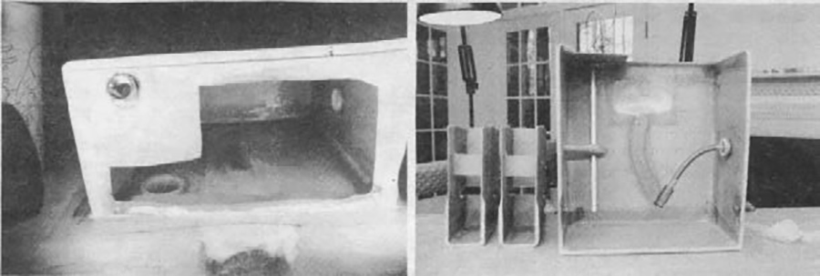
A center line location does not work for the fuel cap and sleeve if one installs a flop tube. I am glad I waited till the end of the process to install mine, otherwise I would have had a headache. It works much better, after observing the travel of the tube, to install the cap over the aft right quadrant of the tank, so there can never be interference. In my tank, I installed a .032 piece of aluminum between laminates where the flop tube can contact the top and bottom of the tank. I have no information that this is necessary but the weight was minimal and I do not ever want to deal with the problem of the flop tube abrading through the fiberglass wall. Talk about a headache! Photos of the header tank and rudder pedal structures are seen above. Harold Shehane (G-I builder) assisted me in bonding the tank in place.
Rudder pedals
The rudder pedal structures can be produced with a similar technique. The keys here are producing a very accurate template for the side walls and jigging the structure in place in the fuselage while the aft wall of the structure is bonded to the side walls so that the dimensions and parallelism of the sides is fixed permanently. The principal advantage of this technique (aside from being easier) is that one can bond the structures in place, one at a time. This allows the builder to install one structure, then clamp the hardware assembly in place while the other is being prepared and bonded in. In so doing, one avoids the specter of a nasty surprise when one is ready to mount the rudder pedal assemblies, and can verify the distance between the tabs, etc.


