This builder mod has been authored by André Beusch.
The circuit described below can be used in the Glasair to replace the solenoids circuit provided with the kit.
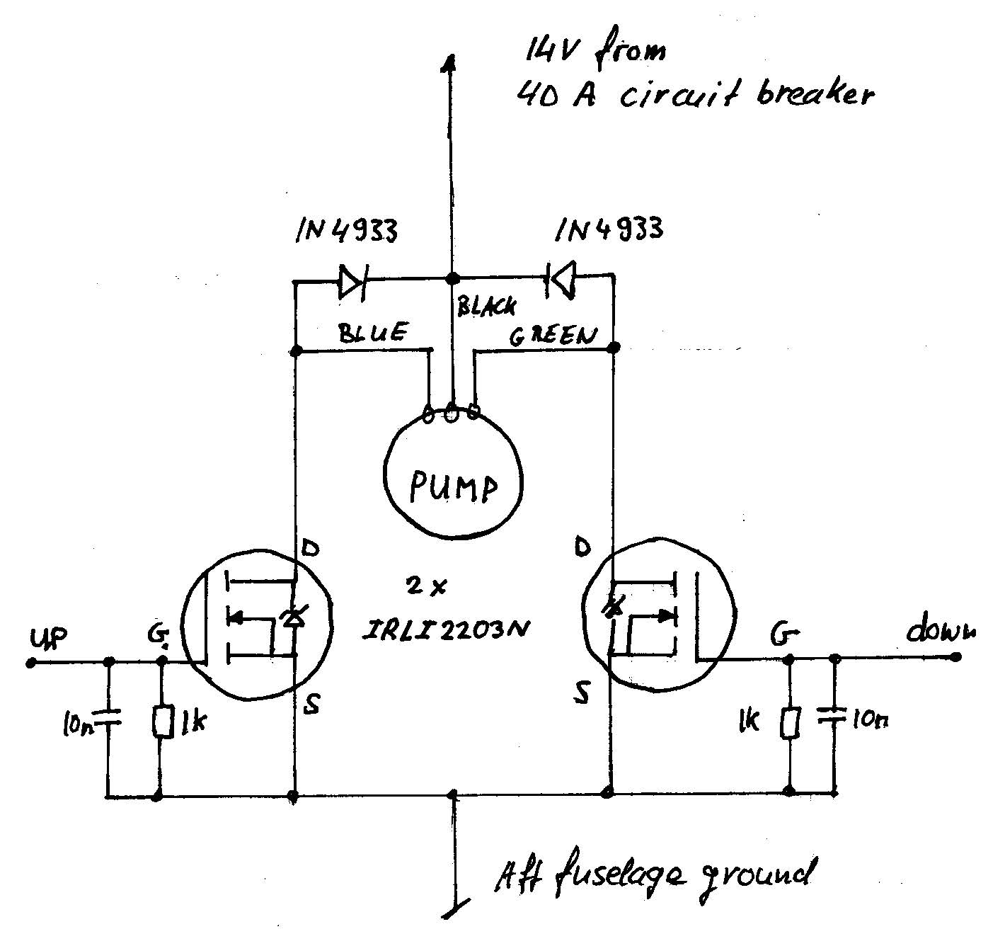
It uses inexpensive power MOSFETs (Metal Oxide Silicon Field Effect Transistor) to switch the motor current. I have chosen a device from International Rectifier which has a very low resistance of 0.007 Ohms when switched on. Since only N-channel devices are possible with very low resistance, the circuit of the pump has to be inverted, +14V being now the common connection (black) instead of ground. This does not change the behaviour of the pump, not even the direction of rotation is changed if the current flows in the reverse direction.
The device is the IRLI2203N, datasheets are available from the website.
Notice the “I” in the device name, referring to the fact that the case is isolated from the pins, and therefore can be directly screwed to a metallic radiator. Not much heat is generated.
There is also a IRL2203N (without “I”), which would require electric isolation between the case and radiator.
Although the MOSFETs have internal clamping diodes, I have added clamping diodes across the motor windings. I have used the diodes provided in the kit for the solenoids, mine were of type 1N4933. Any 1N4933 through 1N4937 would be OK.
1 kΩ resistors hold the gates of the transistors down while 10 nF capacitors filter RF energy that might have been captured by the cables. Use a good quality 1/2 Watt metal film resistors. Use ceramic capacitors with at least 30 Volts ratings. These parts protect the circuit against spurious switching, when transmitting on VHF for instance.
All these parts should be easy to obtain from some electronics distributors, such as newark.com or digikey.com
It is very important that the circuit is assembled with extreme reliability as objective, it must withstand the adverse environment of an aircraft and should require no maintenance.
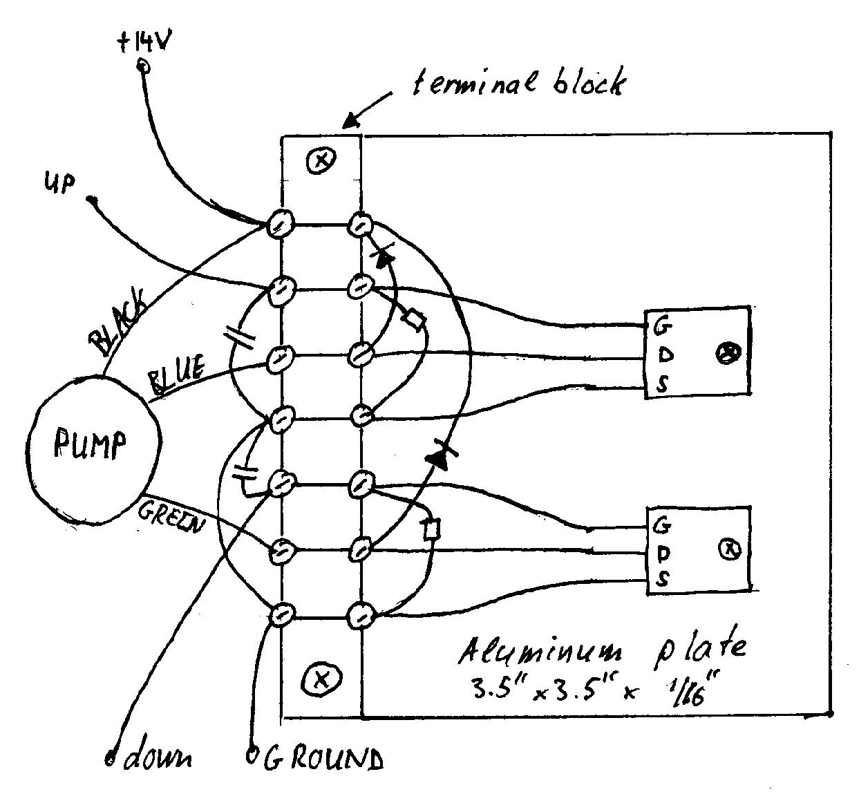
To build a single unit, I recommend to wire the circuit around a terminal block. Simply solder a short piece of aviation wire to the electronic parts, secure the solder joint with heat shrink tubing. Crimp ring tongue AMP terminals on the wires and use the terminal block to do the connections. Use tie-wraps or silicone rubber to prevent any part from moving or vibrating.
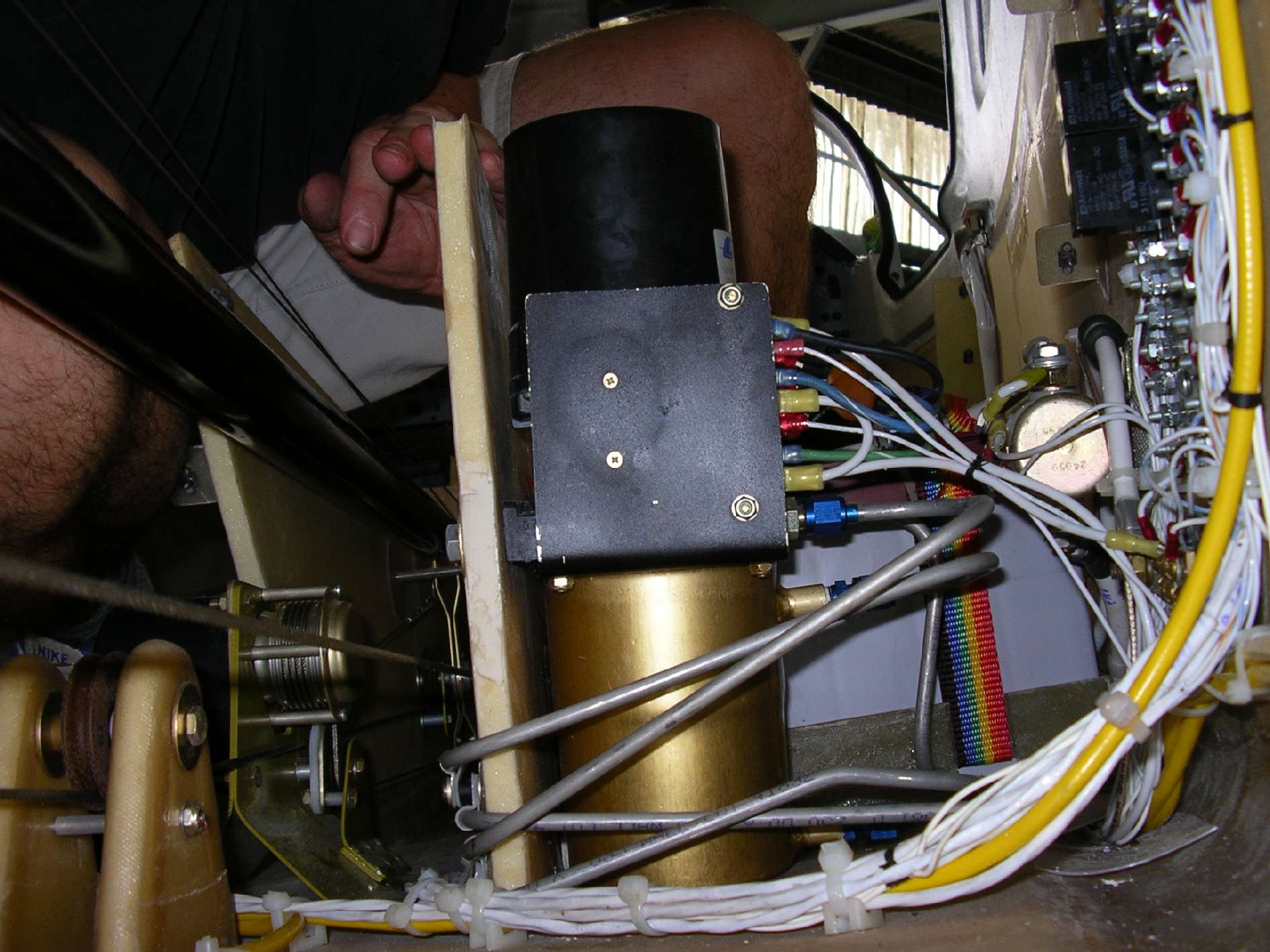
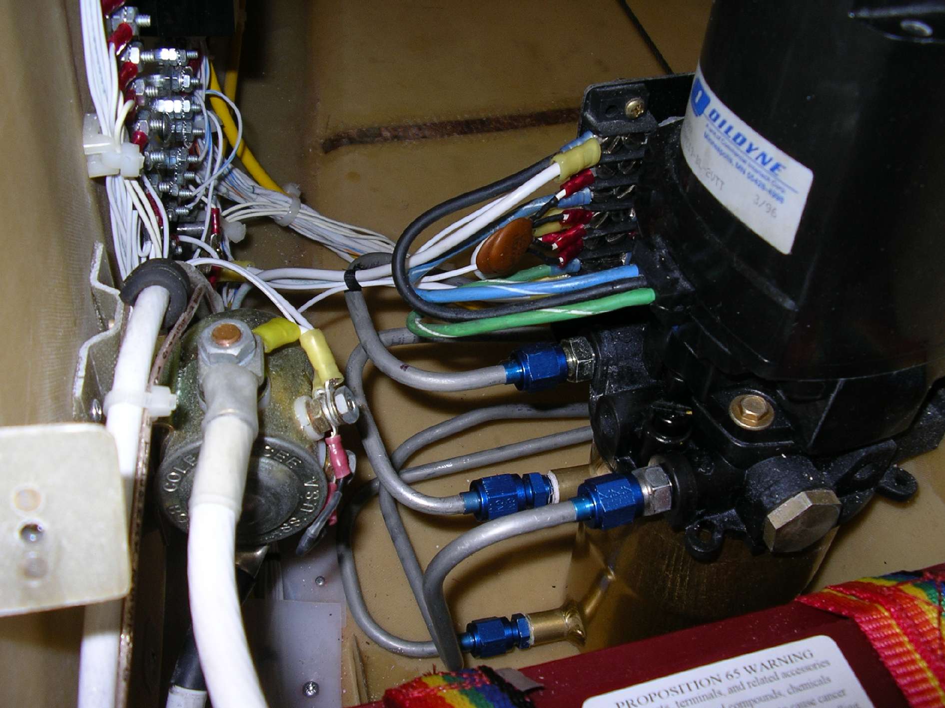
For my airplane, have bent the end of the plate and attached it directly to the side of the pump, see the pictures.
Connect the wires as you would connect the solenoids. Use AWG10 for 14V and ground circuits.
Up to: <PC board up solenoid>
Down to: <PC board down solenoid>
+14V to : +14V from the 40 Amps circuit breaker
Ground to: aft ground bus
The aluminum plate serves both purposes of holding things together and providing cooling for the transistors.
It is important that the resistors and capacitors are close to the transistors, less than about 2″.
The system should be tested on the bench before being built into the airplane. You can use a car battery and headlight bulbs to simulate the pump. When you connect the up or down inputs to the positive terminal of the battery, the corresponding bulb should light. If the input are left open, no bulb should be lit.