 This was the Glasair Options catalog as it was available on Glasair Aviation’s website and is preserved here for archival purposes. A PDF version of the same information can also be downloaded here, and the web pages can be viewed on the Internet Archive (Wayback Machine) website.
- Factory New Certified & Experimental Aircraft Engines
- Firewall Forward Options
- Props, Spinners, Governors, & Cowling Information
- Engine & Flight Instruments
- Avionics, Headers, & Intercoms
- Cabin & Cockpit Accessories
- Airframe Accessories
- Electrical Options & Accessories
- Tools & Supplies
- Safety Equipment
- Miscellaneous
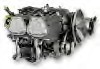
Factory New Certified & Experimental Aircraft Engines
| LYCOMING FACTORY NEW EXPERIMENTAL ENGINES | ||
 |
All fuel injected engine models are available with either Precision Silver Hawk or Airflow Performance fuel injection components. | |
| Lycoming YIO-360-B1E (180 hp)
This injected engine, which includes two traditional Slick magnetos, is the engine of choice for the Glasair II, II-S, and Super II models. |
Part No: 221-0360-101X |
|
 |
Lycoming YIO-360-B1E w/Lasar Ignition
Advertisement
This engine configuration includes the Unison Lasar electronic ignition system (which is fully certified by the FAA). The Lasar ignition system retains one mechanical magneto for redundancy, but replaces the other with a sophisticated electronic ignition module featuring computer-controlled spark advance. Benefits of the Lasar system include better fuel economy and higher power output, particularly at altitude. |
Part No: 221-0360-103X |
| Lycoming YIO-360-C1D6 (200 hp)
All 200 hp installations require cowling modifications due to the wider cylinders. We do not carry an oil cooler for the 200 hp. |
Part No: 221-0360-102X |
|
| Lycoming YIO-360-C1D6 w/Lasar Ignition
All 200 hp installations require cowling modifications due to the wider cylinders. We do not carry an oil cooler for the 200 hp. |
Part No: 221-0360-104X |
|
 |
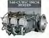
Lycoming YIO-540-K1H5 (300 hp)
This injected engine is the engine of choice for the Glasair III. |
Part No: 223-0540-101X |
|
LYCOMING FACTORY NEW CERTIFIED ENGINES |
||
 |
Lycoming IO-360-B1E (180 hp)
This injected engine, which includes two traditional Slick magnetos, is the engine of choice for the Glasair II, II-S, and Super II models. |
Part No: 221-0360-101 |
 |
Lycoming IO-360-B1E w/Lasar Ignition
This engine configuration includes the Unison Lasar electronic ignition system (which is fully certified by the FAA). The Lasar ignition system retains one mechanical magneto for redundancy, but replaces the other with a sophisticated electronic ignition module featuring computer-controlled spark advance. Benefits of the Lasar system include better fuel economy and higher power output, particularly at altitude. |
Part No: 221-0360-103 |
 |
Lycoming IO-360-C1D6 (200 hp)
All 200 hp installations require cowling modifications due to the wider cylinders. We do not carry an oil cooler for the 200 hp. |
Part No: 221-0360-102 |
 |
Lycoming IO-360-C1D6 w/Lasar Ignition
All 200 hp installations require cowling modifications due to the wider cylinders. We do not carry an oil cooler for the 200 hp. |
Part No: 221-0360-104 |
 |
Lycoming IO-540-K1H5 (300 hp)
This injected engine is the engine of choice for the Glasair III. |
Part No: 223-0540-101 |
Terms re Engine Purchases:
Prices are valid for orders received prior to October 1, 2013 covering engines scheduled for shipment from Lycoming’g factory during the 2013 calendar year. Engines are shipped to U.S. customers directly from the manufacturer – Textron Lycoming. International customers have the option of requesting shipment via Glasair Aviation USA, LLC so that engine orders can be shipped along with kit shipments. Lead times are typically 12 to 16 weeks. Please plan your order accordingly.
A 25% non-refundable deposit is required at the time of order for all engine purchases, with the balance due in full one month prior to projected delivery date.
Our Lycoming engine configurations include: magnetos (or optional Lasar ignition), spark plugs and ignition harness; a Skytech lightweight starter; and, a fuel injection system. All engines are configured for installation on the Glasair airframe with little or no modification. Note: Special, long-term storage packaging is available for an additional $200.00. (Lycoming warrants long term packaging for 6 months.)
Warranty:
Textron Lycoming’s warranty is very detailed, but in brief it warrants each new engine to be free from defects in material and workmanship appearing within 2 years from the date of first operation, excluding necessary acceptance testing. The date of first operation must not be later than 2 years from the date of shipment from Lycoming. In addition, if the engine proves to be defective in material before the expiration of Lycoming’s recommended time between overhaul (TBO) or within 2 years of the date of the first operation, whichever comes first, Lycoming will reimburse the purchaser for a pro rata portion of the engine’s cost.
The warranty covers major parts of the engine, which is limited to the crankcase, crankshaft, camshaft, cylinders, connecting rods, pistons, sump, accessory housing and gears. The proration policy does not extend to labor or to accessories.
FIREWALL FORWARD OPTIONS
|
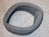
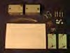
Shock Bushing (Vibration Isolator) Kit For Engine Mount These bushings fit between the engine and the engine mount for engine shock mounting and vibration isolation. A set of four is required for engine installation. For Lycoming O-320, IO-320, O-360, IO-360 and IO-540 engines. Not included in Glasair II or III kits. Aerobatic mounts provide greater shear strength for superior engine retention under high G loads; standard mounts are softer for better vibration damping. Kits include a set of four mounts, bolts, nuts, washers, and cotter pins. Weight 2.0 lbs. per set. I/II TD/FT Conical/Flat |
Part No: 221-6230-501 |
| I/II 160 injected | Part No: 221-7402-501 |
| 18 degree Type II Dynafocal standard IO-320 engines I/II 160 injected |
Part No: 221-7402-537 |
| 18 degree Type II Dynafocal aerobatic IO-320 engines I/II 160 carb/180 |
Part No: 221-7402-502 |
| 30 degree Type I standard O-320, O-360. IO-360 engines I/II 160 carb/180 |
Part No: 221-7402-536 |
| 30 degree Type I aerobatic O-320, O-360. IO-360 engines 200 hp Glasair II-S only |
Part No: 222-4011-501 |
| (except FT’s) 30 degree Type I standard IO-360C series engines Glasair III IO-540 standard |
Part No: 223-3804-527 |
| Glasair III IO-540 aerobatic | Part No: 223-3804-510 |
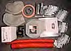
| Engine Baffling Kit
The most complete baffling assembly on the market! It literally comes ready to bolt onto your Lycoming engine and is a real time saver! Made of attractive gold chem. treated 6061-T4 aluminum, it comes with ignition wire clamps, garlock rubberized cowling seal, and over 230 installation hardware pieces such as rubber grommets, threaded rods, nutclips, standard and blind rivets, screws, bolts, high-temp lock nuts, spacers, washers, etc. This baffling forms a plenum chamber in front of the engine by sealing vertically downward onto the lower cowling to provide more even cooling across all the cylinders. A fire retardant fiberglass piece is used behind the alternator because of the complex shape requirements in that area. Complete installation instructions included. |
|
| 150-160 hp | Part No: 221-0132-516 |
| 180 hp | Part No: 221-0132-518 |
| 200 hp | Part No: 221-0132-520 |
| 300 hp | Part No: 223-0132-530 |
| Oil Cooler Kit
An oil cooler is an essential part of the Glasair engine installation. This kit ducts cooling air from the engines baffling to the oil cooler which is mounted on the firewall (I, II) or the inside of the lower cowling (III). The kit includes a new oil cooler matched to the particular engine, a molded fiberglass hood that directs the cooling air over the cooler, a fiberglass oil cooler air inlet duct (III), a 3″ (I, II) or 4-1/2″ (III) flexible hose, Aeroquip oil hose and fittings, and all hardware necessary for a complete Glasair installation. Detailed instructions are included. Kit weight: 6-3/4 lbs.; oil cooler weight (dry): 4 lb. |
|
| 160/180 hp | Part No: 221-0469-501 |
| 250/300 hp | Part No: 221-0469-502 |
 |
Air Filter Element Normally Aspirated |
Part No: 620-0110-001 |
| Injected Engine Induction System
This system, designed for Glasair I, II and III models, it supplies induction are through a NACA scoop and a Brackett air filter system, or through an automatically opening alternate air door in the event of induction icing. This kit comes complete with a pre-molded induction box which bonds to the left inside of the lower cowling, a chemically treated air filter element, required materials, hardware, and instructions. 160, 180, 200 and 300 hp installations use this system. |
Part No: 221-6011-501 |
|
 |
Carbureted Engine Induction System
This system utilizes a NACA inlet on the left side of the cowling and our standard air filter, similar to the one installed on the Glasair III. It provides better air distribution to the cylinders improving engine operation. System included pre-molded induction box, chemically treated air filter element, a mixing manifold assembly, heat muff and related material, hardware and instructions. |
|
| Induction for II RG (I, II, II-S, Super II) | Part No: 301-0136-501 |
|
| Induction for II FT (I, II, II-S, Super II) | Part No: 301-0135-501 |
|
 |
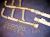
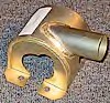
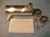
90 Degree Induction Elbow Installation
Custom manufactured pre-welded assembly, made of quality steel tubing, includes welded-on supports for your throttle and mixture control cables. Attractively cadmium plated for added corrosion protection. This induction elbow is ready to bolt on between the injector throttle body and the engine sump for models equipped with injected fuel systems. Includes gasket and installation hardware. |
|
| 160/180 hp Injected | Part No: 221-1470-501 |
|
| 200 hp Injected | Part No: 221-1470-503 |
|
| 300 hp Injected | Part No: 223-1470-101 |
|
 |
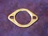
Induction Gaskets
180 Induction Elbow Part No: |
Part No: 221-0066-224 |
| 300 Induction Elbow | Part No: 223-0073-032 |
|
| Induction System FLEX Coupling – Glasair III
No more dealing with scat tube wire ends and unraveling cord. These custom molded flex couplings allow for engine movement, yet simplify the installation and removal of the lower cowling. |
Part No: 623-6030-001 |
|
 |
Stainless Steel Exhaust
For Lycoming engines. Includes carburetor heat muff (except on models for injected engines) and cabin heat muffs. Estimated life: 1,000 – 2,000 hours. These quoted are for Glasair I, II-S. II replacement exhausts are available. Note Glasair III requires separate Cabin Heat muff PN 383- 0803-501 |
|
| Model: For IO-320 150/160 h.p. | Part No: 252-0285-506 |
|
| Model: For O-360 180 h.p. | Part No: 252-0285-507 |
|
| Model: For IO-360 180 h.p. | Part No: 252-0285-508 |
|
| Model: For IO-360C 200 h.p. | Part No: 251-0285-505 |
|
| Model: IO-540 300 h.p. | Part No: 253-0285-505 |
|
 |
Exhaust Gaskets (Spiral Wound)
These gaskets have a unique design incorporating a V- shaped spiral wound insert made of layers of stainless steel and asbestos. This allows expansion and contraction through a wide range of heat and vibration. One gasket per cylinder is used. They offer maximum longevity and may even be reused; for example, after temporary removal and replacement of an exhaust stack. Applicable to all Glasair models. |
Part No: 250-1000-001 |
 |
Fuel Pump Cooling Shroud |
Part No: 331-0165-101 |
 |
Cooling Shroud Installation
This fuel pump shroud is required as a heat shield and to contain cooling air from a blast tube. The shroud mounts to diaphragm-type engine driven mechanical fuel pumps on all Lycoming carbureted or injected engines. This welded aluminum assembly is attractively anodized for maximum corrosion protection. Applicable to all Glasair models, including G-III’s with diaphragm pumps. Installation includes shroud, clamps, instructions, flange, rivets, and aeroduct hose. Weight: .18 lb. |
Part No: 331-0165-501 |
 |
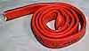
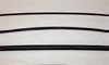
Aeroduct Hose
Aeroduct “SCAT” type flexible tubing is constructed of a single ply of red silicone rubber impregnated fiberglass with a copper coated steel wire inside and wrapped with fiberglass cord on the outside. It will withstand temperatures from -80 (all prices are per foot, please indicate # of feet needed) |
|
| SCAT Tube Size 1″ | Part No: 830-0004-001 |
|
| SCAT Tube Size 1-1/2″ | Part No: 830-0006-001 |
|
| SCAT Tube Size 2″ | Part No: 830-0008-001 |
|
| SCAT Tube Size 3″ | Part No: 830-0012-001 |
|
| SCAT Tube Size 4″ | Part No: 830-0016-001 |
|
| SCAT Tube Size 4-1/2″ | Part No: 830-0018-001 |
|
 |
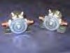
Cabin Heat Valve
The rotary valve unit is designed to be installed on the cockpit side of the Glasair firewall. It is designed with two cabin heat outlet tubes (one for the pilot and one for the co-pilot) and a single outlet tube for windshield defrost. In the off position two openings forward of the firewall allow heated air traveling form the exhaust heat muff to be vented into the engine compartment, avoiding hot spots inside the heat muff. Very accurate, smooth control of cabin heat air is accomplished through the unique rotary action. As the center tube continues to rotate, the cabin heat slots will continue to open then begin to close as the defrost slot opens offering a desired metering between cabin heat and defrost. For those who have modified their firewall from original design specifications, a 3 3/4″ horizontal distance is required between the aft face of the firewall and the forward most point of movement on the rudder pedal assembly. The Cabin Heat Valve Assembly may be purchased separately or as a complete installation including all hardware, spun aluminum flange, and 11 feet of SCAT tubing. Weight 9.1 oz. |
|
| Cabin Heat Valve Assembly | Part No: 471-0810-201 |
|
| Cabin Heat Valve Installation | Part No: 381-0142-503 |
|
 |
Cabin Heat Muff – G-III
Glasair III customers stop wearing those long johns; heat has finally arrived to your cabin area! This kit includes a specially designed cabin heat muff assembly with instructions and hardware necessary for a clean installation. The cabin heat valve that mounts in the firewall must be purchased separately. |
Part No: 383-0803-501 |
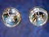
| Landing Light Kit
This kit includes a 4″ diameter, 100,000 candle power aircraft landing light, an aluminum retainer ring, a formed aluminum housing, a clear plexiglass lens (heat formed to fit the curvature of the cowling with a stepped flange to permit easy flush fit installation), wire, wire terminals, anti-chafe spiral wrap, clamps, quick disconnect terminals, all hardware necessary for installation, and detailed installation instructions. Kit does not include switch or circuit breaker. The Glasair II and III kits, listed below do not include the plexiglass lens since this part is included with the airframe kit. Kit weight: 1.3 lb. |
||
| Glasair I, Long Cowl | Part No: 211-0125-501 |
|
| Glasair I, Short Cowl | Part No: 211-0125-502 |
|
| Glasair II/II-S/Super II | Part No: 212-0125-501 |
|
| Glasair III – 14 V | Part No: 213-0125-501 |
|
| Glasair III – 28 V | Part No: 213-0125-502 |
|
| CP-25 Fire Barrier Caulking*
Manufactured by the 3M Corporation, CP-25 replaces the previously recommended RTV-88 silicone sealant for use as a fire barrier caulking. Since CP-25 expands to fill voids caused by the shrinkage of other materials, it is preferred for use with materials that shrink when exposed to heat. Due to shelf life, order this product at the time of need. Included with Glasair II and III kits. 10-1/2 fl. oz. tube. |
Part No: 270-0132-001 |
|
 |
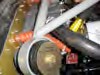
Fire Sleeve Used to fire protect fuel lines in the engine compartment to FAR standard for certificated aircraft. |
Part No: 830-0102-012 |
| High-Temp. RTV Silicone Sealer
Capable of withstanding temperatures of up to 650 degrees F, this pliable sealer has many uses both forward and aft of the firewall. Price is for a 3 oz. tube. |
Part No: 270-0026-002 |
|
 |
Air Duct Flanges
Aluminum Flanges: Lightweight; for attachment of duct hose to baffling, etc. Easy to install, may be welded or riveted. Attractively anodized for maximum corrosion protection. |
|
| 1″ Diameter x 1-1/4″ | Part No: 610-0142-005 |
|
| 1-1/2″ Diameter x 1-1/4″ | Part No: 610-0142-001 |
|
| 3″ Diameter (for I/II oil cooler) | Part No: 610-0469-001 |
|
| Stainless Steel Flanges: Give extra durability and strength when required. 1-1/2″ Diameter x 1-1/4″ | Part No: 610-0142-003 |
|
| 1-1/2″ Diameter x 2″ | Part No: 610-0142-004 |
|
 |
AeroMag™ AM360 Magnetic Oil Filter System
AeroMag™ traps and holds wear-inducing metal particles that have escaped through the filter. It traps all steel particles from 40 micron down to below 2 micron, helping you reach TBO. The AeroMag™ is constructed from the highest quality components and is completely reusable. No moving parts to wear out. Installation is simple. Strong neodymium magnets secure it to the filter and trap harmful particles with the same powerful bond. Keeps your oil cleaner so it lubricates better, allowing your engine to run cooler. |
Part #: 014-02234-01 |
 |
Magneto Cooling Kit
Help Extend the life of your engine magnetos! This kit includes two hat flanges, 20″ of 3/4″ aeroduct hose and installation hardware to install cooling ducting to both magnetos. This is an easy retrofit to existing engine baffling; requiring a step drill capable of 3/4″ diameter holes, 1/8″ drill bit and a “pop” rivet puller. Estimated installation time is less than one hour. |
Part No: 042-07000-08 |
Props, Spinners, Governors, & Cowling Information
| Constant Speed Propellers for Glasair I’s and II’s
We offer Hartzell constant speed propellers for Glasair I and II aircraft configured with 160, 180 and 200 hp Lycoming engines. Note: The following link to Hartzell has some great information regarding propellers for the Glasair: Hartzell Propellers Please read the terms re Hartzell propellers at the bottom of this page. |
| Extended Hub Constant Speed Propellers | ||
| 72″ Propeller for 150/160 hp
Hartzell No:HCF2YL-1F/F7663D-4/SM19 Installation Weight: 53.6 lbs. |
Part No: 681-0476-001 |
|
| 68″ Propeller for 180 hp
Hartzell No:HC-F2YR-1F/F7068-2/SM8 Installation Weight: 61.5 lbs. Note: The extended hub propellers require the extended hub cowling, (longer cowling). |
Part No: 681-0476-006 |
|
| Non-Extended Hub Constant Speed Propellers | ||
 |
74″ Propeller for 180/200 hp
This 74″ – diameter, Non-extended hub prop produces optimal climb and cruise performance. Operated on the O-360-A1F6, the prop has no RPM restrictions; on the 0- 360-A1A, the prop is restricted from continuous operation between approximately 1900 and 2200 RPM, pending completion of a vibration survey. Note: This propeller can only be used on O-360’s with hollow crankshafts. Hartzell No:HCC2YK-1BF/F7666A-2/SM8 Installation Weight: 55.4 lbs. |
Part No: 681-0476-004 |
| 68″ Propeller for 180/200 hp
Hartzell No:HCC2YR-1BF/F7068-2/SM8 (non- counterweighted crank) |
Part No: 681-0476-007 |
|
| Hartzell Propeller Model HC-C2YR-1BF/F7497
2-BLADE PROPELLER; Available in 74″ OR 72″ diameter HARTZELL “BLENDED AIRFOIL” DESIGN PROPELLER FOR USE WITH LYCOMING 180 HP ENGINES WITH 8.5:1 COMPRESSION PISTONS INCLUDING ELECTRONIC IGNITION AND FADEC Specifications: |
||
| 74″ Version | Part No: 681-0476-008 |
|
| 72″ Version | Part No: 681-0476-009 |
|
| MT-Propellers for Glasair
All propellers are variable pitch, constant speed. Recommended governors for all hydraulic propellers: McCauley, Hartzell, Jihostroj and Woodward. Compatibility with our propellers must be confirmed. Generally we recommend the use of hydraulic propeller system because of it’s higher pitch change rate (~6 times). If a hydraulic system is not possible the electric constant speed propeller is recommended. Take off, climb and cruise performance of both systems is equal, if the same blade types are used. If the Lycoming IO-360 is selected as the preferred engine, we’d recommend the version which has 6th-order dampers installed (i.e. -A1B6) for lower vibration loads. Our propeller blades are manufactured in natural-composite, protected by two layers of fiberglass and a stainless-steel erosion sheet, hubs made from aluminum alloy, Kevlar spinner dome. Extended hubs – if required – are available on request, at no additional charge. Standard blade colour is white with red tips, customer defined colours upon request. See our Service Bulletin No. 1-() for the current TBO’s. All quoted prices are list prices for the export, ex factory Straubing. Our general terms of sales and limited warranty applies. The shipping box for the 2-blade propellers is included in the price. For assembled 3-blade propellers the shipping box costs US$ 200.- net additionally. Delivery time is presently 8-10 weeks after receipt of order. All rights of change without prior notice are reserved. |
||
| Glasair I and II with the Lycoming (I)O-320 engine:
71″ dia 35 lbs icnl. Spinner P-294 (without governor) 2- blade hydraulic |
Part No: 502-04100-01 |
|
| 71″ dia 43 lbs incl. Spinner P-237 (without governor) 3- blade hydraulic | Part No: 502-04300-01 |
|
| Glasair I and II with Lycoming (I)O-360 engine:
72″ dia 44 lbs incl. Spinner P-271 (without governor) 2- blade hydraulic |
Part No: 502-05200-01 |
|
| 71″ dia 45 lbs incl. Spinner P-368 (without governor) 3- blade hydraulic | Part No: 502-05400-01 |
|
| Glasair III with Lycoming (I)0-540 engine:
76″ dia 57 lbs incl. Spinner P-282 (without governor) 3- blade hydraulic |
Part No: 502-08300-01 |
|
| 76″ dia 65 lbs incl. Spinner P-282 (without governor) 3- blade hydraulic counterweighted | Part No: 502-08500-01 |
|
| 75″ dia 60 lbs incl. Spinner P-238 (without governor) 4- blade hydraulic | Part No: 502-08700-01 |
|
| Sensenich Fixed Pitch Propellers for Glasair I’s and II’s – 160 h.p.
Designed for the Glasair, this 70″ propeller has a 77 degree pitch and performs slightly better than the Pacesetter wood propeller, model 68-71-20 in both cruise and climb. Its main advantages however are in longevity and smoothness (restricted to 2600 RPM redline). Please allow 8 – 10 weeks for the Sensenich factory to ship direct to you. Comes with mounting bolts and propeller extension to be used with the long cowling. The spinner mounting kit will be extra. The following link to Sensenich has some great information regarding propellers for the GlaStar: Sensenich Propellers |
||
| Sensenich No: 70CM7S16-0-77 (7/16″ Bolts) | Part No: 681-7077-101 |
|
| Sensenich No: 70CM6S16-0-77 (3/8″ Bolts) | Part No: 681-7077-102 |
|
| FIXED PITCH PROPELLER EXTENSIONS AND CRUSH PLATES
(Not for use with the Sensenich metal propeller.) These items are drop shipped from the manufacturer and are usually in stock for immediate shipment. Hybrids, such as for adapting an SAE-1 prop to an SAE-2 engine, as well as custom lengths are also available. Please call us for current pricing if interested. There have been failures of 6061 T-6 prop extensions, too brittle for the application, and therefore subject to fatigue. All of these prop extensions are machined from solid 2024 T-351 aluminum billet, for strength and fatigue resistance. They are also guaranteed to be completely free of tool marks and chatter by the manufacturer. Since our lugs are internally threaded, the use of nuts and washers are unnecessary. The prop bolt screws directly into the internally threaded lug. Consequently, you can remove the propeller or re-torque the bolts without removing the upper cowling to access propeller nuts. These prop extensions are available in either 6′ or 7′ diameter and are 4″ long to match our long cowling. The 6″ prop extension has 5/8″ threaded lugs installed. The engine end is counterbored for 5/8″ lugs and 3/8″ or 7/16″ bolts. Please specify bolt and thread size of the lugs/prop bolts when ordering or requesting information. The 7″ prop extension has ¾” threaded lugs installed with ½-20 thread. The engine end is 6″ in diameter and counterbored for 5/8″ or ¾” lugs. You will need to specify lug size when ordering or requesting information. Propeller crush plates are also available. The 6″ O.D. crush plate comes 3/8″ thick, SAE-1, or –2, with 3/8″ or 7/16″ holes. The 7″ O.D. crush plate comes 3/8″ thick, SAE-2, with 3/8″ or 7/16″ holes. Please specify hole size and any other information needed at time of ordering or requesting information. |
||
| Constant Speed Propellers for Glasair III’s
For additional information on propellers for the Glasair III go to: Hartzell Propellers |
||
| GIII Hartzell Propeller
Hartzell No:HCC2YK-1BF/F8475J-4/SM19 Hartzell designed a factory optimized blade twist to provide more thrust for the Glasair III. |
Part No: 683-0476-001 |
|
| Jihostroj Governor
Glasair Aviation also carries the Jihostroj governor. Compact design and light, 2 lbs weight. |
|||
 |
Wide deck IO540 | Part No: 683-0210-763 |
|
 |
160-180-200 hp | Part No: 681-0210-050 |
|
| Cowling Selection | |||
| Cowling Installation Kit:
FT/TD Glasair models |
Part No: 302-0150-504 |
||
| Cowling Installation Kit:
RG Glasair models |
Part No: 302-0150-503 |
||
| Spinner Selection | |||
| Sensenich Fixed Pitch Propeller Spinner Kits:
3/8″ diameter installation bolts |
Part No: 301-0260-506 |
||
| Sensenich Fixed Pitch Propeller Spinner Kits:
7/16″ diameter installation bolts |
Part No: 301-0260-507 |
||
|
Wood Fixed Pitch Propeller Spinner Kits – Glasair I/II: Note: Several different manufacturers make wood fixed pitch propellers; however, Glasair Aviation does not stock a wood propeller nor do we stock the extension required to install the wood propeller. |
Part No: 301-0260-504 |
||
|
Hartzell Controllable Pitch Propeller Spinner Installation Kit |
Part No: 301-0260-501 |
||
| Hartzell “Compact” Hub Propeller Spinner Kit | Part No: 301-0260-502 |
||
Terms re Hartzell Propeller Purchases:
Standard delivery time for Hartzell propellers is about 12-16 weeks from the date of order. A 25% deposit is required to be paid to Glasair Aviation, LLC at the time of order with the balance to be paid in full 30 days before shipment. Propellers are drop-shipped freight collect directly from Hartzell.
Propellers must be shipped in calendar year 2012 to qualify for this pricing. November 15, 2013 is the approximate order cutoff date to qualify for 2013 shipment.
Hartzell’s factory warranty covers defects in material and/or workmanship for the first 1000 hours or for a period of one year from when first installed, whichever occurs first. Hartzell constant speed propellers also have a maximum shelf life of 2 years, after which Hartzell, in Service Letter 61-P, highly recommends that the seals be replaced.
Engine & Flight Instruments
| Future Vision Instrument Panel
This instrument panel is extraordinary. No panel has ever been designed for conventional aircraft that can even remotely compare to this one. First introduced at Sun ‘n Fun by Lance Turk, owner and founder of Vision Microsystems. Lance designed and installed the panel into his Glasair I FT to provide a true state-of-the-art backdrop for his instruments. This panel was instrumental in Lance winning the “Best Interior” award at the show. Because of the flood of inquiries received from builders who have seen the panel first-hand, Glasair Aviation, LLC now has made available a kit which includes one piece fiberglass panel, aluminum inserts for all your instruments, and all the hardware such as stainless steel cap screws, aluminum rivets, and steel nutplates for mounting the inserts to the panel and the panel to the fuselage. The installation comes complete with instructions as well as sample instrument layouts. NOTE: Glasair I’s are able to install the II/II-S instrument panel, but some modification is required to enable the 3 inch wider panel to fit. Also be aware that minimal panel space may be lost due to this modification, in particular the upper left hand corner. Additional instructions and photographs are included with the Glasair I orders. |
||
| Glasair II/II-S | Part No: 302-0354-501 |
|
| Glasair III | Part No: 302-0354-501 |
|
| Glasair I | Part No: 302-0354-501 |
|
| Custom Labeling
Custom labeling for instrument panels and rocker switches are available direct through Aircraft Engravers, phone (203) 653-2780, fax (203) 654-7324. If you have seen or read about Ken Johnson’s Grand Champion Glasair III, these are the folks that provided his labeling. Call them for more information. |
||
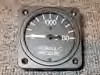 |
Hydraulic Gage
This gauge will keep you alerted to the pressure occurring in your retract system. This 2-1/4″ gauge measures from O-2000 psi in easily read graduations. Normal system operating pressures range from )-1950 psi. (NOTE: 3000 psi gauges previously supplied are not longer available). |
Part No: 340-0349-001 |
| Hydraulic Shuttle Valve Kit
The retractable gear hydraulic pressure gauge normally displays hydraulic pressure only on the down side of the system to verify proper operation for gear extension. The hydraulic shuttle valve kit allows a single hydraulic gauge to automatically show pressure on both the up and down sides of the system. The valve is installed with “T” fittings between the hydraulic lines on the nose gear box, and then is plumbed with a single line to the pressure gauge. The kit includes the valve, all necessary hardware, and installation instructions. Applicable to all retractable gear Glasair models. |
Part No: 341-6277-501 |
|
Avionics, Headsets, & Intercoms
| LightSpeed QFR XC2 Headset
10-12 dB of Active Cancellation 24-26 dB of Passive Attenuation Exclusive AES Battery ‘Time Out’ Auto Shut-Off Aux Audio Input Significant reduction in the 120-200Hz range Additional active attenuation out beyond 600 Hz Small In-Line Battery Control Box Two ‘AA’ batteries provide 25 hours of operation Battery Status Indicator Dual volume controls, stereo/mono selection and a LED battery “fuel gauge” to monitor usage Reversible Boom Allowing for Left or Right Side Operation Adjustable Gain Pre-amp Allowing for Field ‘Balancing’ of Mic Sensitivities Color: Black 3 Year Warranty from LightSpeed |
Part No: 121-3010-01 |
| LightSpeed Thirty 3G Headset (battery powered)
28-30dB of Active Cancellation 12-22dB of Passive Attenuation Exclusive AESTM “Auto Shut-Off” powers down the Active Electronics if system is left unattended. Personal Side-Tone EQ with Bass and/or Treble Boosting Cell Phone Interface Auxillary Audio Interface Weighs under 16 ounces ANR Power for 14-24 Hours on just Two AA Batteries Independent left and right ear volume controls Stereo-or-mono switchable Temperature Sensitive Confor-Foam Ear Seals Padded Headset Bag, Mic Wind Screen, and (2) AA Batteries Included. Interface Cables for Music / Cell Phone Low battery indicator Color: Blue 3 Year Warranty from LightSpeed |
Part No: 121-3020-01 |
|
| LightSpeed Thirty 3G Headset (panel powered)
The Quietest LightSpeed Has Ever Made! 28-30dB of Active Cancellation 12-22dB of Passive Attenuation Exclusive Glastar, Sportsman or Glasair Logo available on each ear-cup! Exclusive AESTM “Auto Shut-Off” powers down the Active Electronics if system is left unattended. Personal Side-Tone EQ with Bass and/or Treble Boosting Cell Phone Interface Auxiliary Audio Interface Weighs under 16 ounces Panel Powered, single cord Independent left and right ear volume controls Stereo-or-mono switchable Temperature Sensitive Confor-Foam Ear Seals Padded Headset Bag, and Mic Wind Screen Included. Interface Cables for Music / Cell Phone Color: Grey 3 Year Warranty from LightSpeed *to purchase the panel receptacle (Lemo Redel part number PTG.M0.6NL.LC65N) contact Earle & Brown @ 425-885-5064. |
Part No: 121-3030-01 |
Cabin & Cockpit Accessories
| Passenger Side Brake Kit
All Glasair I, II, and III kits include a pilot side brake system only (except for early Glasair I’s which did not include any brakes). This kit is designed for those wanting braking functions on the passenger side as well. Includes two Cleveland master cylinders, two rudder pedals, fittings, and (for the Glasair III) extra hose. *NOTE: A full width Header Tank, as shown in Figure D-54, page D-92 Vol I of the Glasair III Manual, cannot be used with this option. Instead, purchase the Dual Brake Kit – Large Header Tank Installation listed on the next page. |
|
| Model: I/II TD and FT | Part No: 901-0139-503 |
| Model: I/II RG | Part No: 901-0139-504 |
| Model: Glasair III* | Part No: 903-0139-501 |
| Model: Super II TD/FT/RG | Part No: 902-0139-501 |
| Dual Brake Kit – Large Header Tank
If you have built a larger than normal header tank that extends across the passenger side, the standard dual brake installation will not be possible. To accommodate this configuration we have developed a Dual Brake Kit that attaches the master cylinders to the bottom of the header tank. |
|
| GII-S | Part No: 902-0141-501 |
|
| GIII | Part No: 903-0141-501 |
|
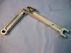
| Rudder Pedal Brake Actuating Arm Extension Kit
This kit lengthens the brake master cylinder actuating arm on early Glasair I RG, II RG, and III rudder pedals. The longer lever arm increases the length of the master cylinder stroke which eliminates the “spongy” feel of the brakes and substantially improves braking effectiveness. These are in later model Glasair RG and III Kits, shipped after 5/1/89, which have different pedal castings. |
Part No: 381-0530-501 |
|
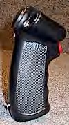 |
Control Stick Grips
These stick grips are superb quality, made of black molded hard plastic with red switches. “Glasair” is attractively molded into the top of the handle (except on the military type grip). Two styles are available: civilian type (#’s 1451, 1452, 1453), and military type (#1460). The neutral military stick will fit either hand and comes with one trigger switch only, the remaining three switch positions are left unfilled and switches may be added by the builder, if desired. The other grips come with the switches described. Switch functions may be used for intercom, radio transmit, auto-pilot disengage, roll trim, etc. Weight: .25 lb. Ea. There is often a lead time on these parts, so order early. *These grips include a sleeve to match the inside diameter of the grip to the outside diameter of the control stick. |
|
| 2 Switch, Rt. Hand | Part No: 621-1451-101 |
|
| 1 Switch, Rt. Hand | Part No: 621-1452-101 |
|
| 1 Switch, Lt. Hand | Part No: 621-1453-101 |
|
| 4 Switch, Neutral | Part No: 621-1460-101 |
|
Airframe Accessories
| Wing Tip Fuel System Kit
This kit is necessary if you choose to make the wing tip extensions into fuel cells holding approximately 5.5 gal. per side. The kit includes (2) flush fuel cap and sleeve assemblies, (18) AN anodized aluminum fuel fittings, (2) fuel drain fittings, (8) welded-flange fuel transfer fittings, (14) feet of aluminum tubing, flexible fuel hose, (12) hose clamps, misc. hardware and detailed instructions. The price of this kit is a substantial savings over buying each piece separately. |
||
| Glasair I/II/II-S/III | Part No: 332-0651-501 |
|
| Clear Wing Tip Lenses
These clear lenses enable you to install your NAV Lamps and strobes within the tips, thus reducing drag. Colored bulbs must be procured for the NAV lights, and a strobe unit installed in the rudder to meet FAR requirements. Glasair Aviation, LLC regrets that we cannot accept original colored lenses back for exchange or credit. |
||
| Hoerner Tip Lt. | Part No: 672-0376-003 |
|
| Hoerner Tip Rt. | Part No: 672-0376-004 |
|
| Extended Wing Tip Lt. | Part No: 673-0377-003 |
|
| Extended Wing Tip Rt. | Part No: 673-0377-004 |
|
 |
Rear Windows
Enhance the aesthetics and rearward visibility of your Glasair with these flush fit rear windows. The premolded pieces follow the contour of the Glasair fuselage and add that extra finishing touch. (Note: Glasair II Rear Windows fit the Glasair I fuselage, but the tint color is slightly different.) Also, the length of I/II rear windows are shorter than the II-S and III rear windows due to the positioning of the baggage bulkhead. Detailed installation instructions are included. Included in Super II and Glasair III kits. |
|
| Glasair II-S/III – Left | Part No: 673-0524-001 |
|
Wing Tip Extensions
These wing tip extensions add four feet to the wing-span which increases the aspect ratio from 6.2 to 7.6. The climb performance is increased by 150 feet/min., stall speed is reduced up to 5 m.p.h., and the lateral (roll) stability is greatly improved for cross-country flying. Our tests consistently show that, at reduced power settings, the extended tips offer greater lift and more speed for the horsepower-approximately a 7 mph increase at 17,500 ft. These tips may be used as integral fuel tanks, with about 5.5 gallons capacity per side. The tip extensions reduce the roll rate from approximately 140 degrees per second to 90 degrees per second and are not recommended for aerobatics. Structurally, they will withstand the design limit and ultimate loads of the Glasair but are not recommended for aerobatic maneuvers due to the reduced roll rate. They are designed to be easily removable and replaced with the smaller, standard wing tips if more aggressive roll performance is desired. Wing tip change-over takes about 10 minutes per side if they are not used for carrying fuel. (Glasair I builders: please note that to make the tip extensions and the standard tips interchangeable, the standard tips will have to be modified slightly to accommodate the larger flange necessary for mounting the tip extensions.) The wing tip extensions are designed with an attractive, upswept Hoerner-type tip, which reduces drag compared to a standard rounded tip. The kit includes molded composite upper and lower extension panels, foam and fiberglass, mounting hardware, fabrication instructions and clear Plexiglas navigation light lenses. NOTE: We highly recommend the use of these wing tip extensions for first flights and initial test flying, especially for Glasair III owners. There are very few rental aircraft available which can simulate the high wing loading of the Glasair III. The wing tip extensions will lower the wing loading to a more familiar level for pilots who lack experience in high performance aircraft. WARNING to Glasair I builders: If you choose to use/install wing tip extensions, it is mandatory that you install the large rudder – reference S.B. #116. Glasair I aircraft equipped with tip extensions may stall below the minimum controllable airspeed (Vmc) as defined in the Owner’s Manual. Thus, if minimum airspeed is not maintained, the small rudder may not maintain adequate yaw control, especially if the tip extensions are used as auxiliary fuel tanks. Note: The Large Rudder is standard in all Glasair Kits shipped after September 1985. NOTE: Includes (1) gallon resin. Resin shipped separately. For use as fuel tanks, see wing tip fuel system kit below. This item shipped C.O.D. or by credit card via United Parcel Service. Please call us for shipping charges if you wish to prepay the freight. Order Form shipping charges are not applicable for this option. 8.2% Washington State Sales Tax required on all pick-up orders. Crating charge applies. |
||
| Glasair I/II/II-S/Super II-S | Part No: 302-0311-501 |
|
| Glasair III | Part No: 303-0311-501 |
|
 |
Fuel Vent Float Valve Installation
The valves are designed to be retrofitable to flying Glasairs. They mount to the outboard side of the main fuel tank end rib, accessible by removing the wing tip or wing tip extensions. Provisions have been designed into them for the connection of extended wing tips with fuel. When the fuel level moves up to the level of the vent, such as when parked on sloping grade, an upside down shaped cup acts as a float and rises to close the vent, preventing the fuel from dumping overboard. As the fuel level drops below the vent, the float unseats and allows the fuel tank to breathe in both directions. A low-pressure relief valve has been incorporated to relieve pressure should fuel expansion occur with full tanks. When there is an engine fuel demand with tanks full, a pressure relief valve will open until the level is below the fuel vent and normal venting can occur. Also, during aerobatics or inverted flight, the cup shaped float will fill with fuel and close the fuel vents preventing fuel from flowing overboard. The kit consists of two fuel vent float valves and the installation instructions. |
Part No: 332-0490-501 |
| Slotted Flaps
The Slotted Flap Installation is undoubtedly one of the best improvements that has been added to the Glasair line in recent history. The benefits of the Slotted Flaps are significant: (1) reduces stall speed by 6 mph, (2) reduces landing and takeoff roll, (3) significantly improves over the nose landing visibility during approach, (4) reduces approach speeds (an invaluable safety feature for a forced, off-field landing), (5) increases maximum flap speed from 120 to 140 mph. With the Extended Wing Tips the Glasair can be truly one of the best high speed cruise performance aircraft, and yet have excellent short field/stall capabilities. Note: Electrical Flaps Installation is required with this option. The Slotted Flaps for the Glasair II, II-S, Super II-S and III kits have a flat, non-cusped bottom to match the ailerons supplied in those kits. Please order accordingly. The slotted flap kit or electric flap option use an external flap position. Customers mark the flaps on their inboard ends and visually read the degrees of actuation by alignment with the trailing edge. The system is very simple and works well. It sure reduces cost, weight and complexity over a traditional cockpit indicator! Note: This option requires $75.00 crating charge. |
|
| Cusped – Glasair I | |
| Non-Cusped – Glasair I | |
| Non-Cusped – Glasair II/II-S/Super-II-S/III | |
 |
Hydraulic Snubber
During operation of our Glasair III prototype, we have experienced higher than normal loads on the hydraulic actuator rod ends caused by aerodynamically assisted gear extension at or above 140 mph. When the hydraulic system moves the actuators to release the mechanical uplock hooks, there is relatively low pressure on the opposite sides of the actuator pistons and very little restriction in the hydraulic fluid’s flow back to the pump. This situation, along with aerodynamic forces and the force of gravity, causes the gear to fall abruptly out of the wing. Achieving smoother gear operation and thereby reducing peak loads on the hydraulic system can easily be accomplished by installing the hydraulic snubber between the “B” cross and the hydraulic pump. The snubber is an AN816-4D nipple that has been modified by welding it closed and then drilling a #60 hole through the weld. The tiny hole restricts the flow of fluid back to the electric hydraulic pump, preventing the gear from slamming down. Standard on all Glasair III kits shipped after January 28th, 1990. |
 |
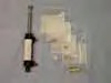
Hydraulic Actuator Rebuild Kits
Hydraulic actuator rebuild kits are available for the hydraulic actuators supplied with the Glasair kits. Each rebuild kit will supply all necessary seals and “O” rings to rebuild one cylinder. Because of different diameter actuator piston rods used by different kits it is very important that when ordering a rebuild kit the type of airplane (G-I, II, II-S or II) and cylinder location (main or nose gear) be specified. |
|
| Glasair III – Main | Part No: 341-5640-501 |
|
| Glasair III – Nose | Part No: 343-5620-502 |
|
| Glasair I/II – Main | Part No: 341-5620-501 |
|
| Glasair I/II – Nose | Part No: 341-5640-501 |
|
 |
Emergency Gear Extension Retrofit – G- III This retrofit kit must be used in conjunction with the side brace down lock system, both of which are standard on all Glasair III kits shipped after S/N 3238 and are a great safety enhancement to the Glasair III’s. The system increases the value of your aircraft and is inexpensive insurance against almost any type of gear system failure. This kit includes a complete backup set of main gear and nose gear hydraulic actuators, a four port selector valve, two check valves, an adjustable restrictor valve, a pressure switch gear pump indicator light, over ride button, and much more. All parts and installation instructions are included. The emergency gear extension system uses a pressure switch on both the up and the down side of the hydraulic system to turn the hydraulic pump off. The electric microswitches only operate the indicator lights, thereby eliminating several possible failure modes, and simplifies troubleshooting. The installation provides a completely independent system for emergency gear extension in the event of total electrical or primary hydraulic system failure. |
Part No: 353-5800-502 |
353-5290-501
|
Side Brace And Down Lock Retrofit Kit – G-III This new system no longer relies only on the side braces moving over center. Now, as the side braces move into over center position, a down-lock hook engages a pin at the side brace knuckle to ensure that the main gear are solidly locked in the over center position. These new side braces also have a larger cross section area for increased strength. This installation is required if the emergency gear extension system is going to be installed. The emergency gear extension system uses a separate, compact and lightweight hydraulic actuator to release the up-lock hook and allow you to manually pump the gear into the extended and locked position. The side braces and down lock installation were standard in Glasair III’s shipped after 9/21/91, Kit #3238. |
|
| Down Lock Component Kit | Part No: 353-5290-501 |
|
| Side Brace Assembly-Lt. G-III | Part No: 353-5205-103 |
|
| Side Brace Assembly-Rt. G-III | Part No: 353-5205-104 |
|

| Brake Upgrade Kits
The Cleveland upgrade kit for the Glasair I, II and II-S converts the Cleveland wheel and brake kit 199-102 to the new heavy duty wheel and brake kit 196- 156. It utilizes a 65% thicker disc for better heat dissipation and a new non- asbestos organic lining. |
||
| Model Glasair I/II/II-S | Part No: 902-0678-201 |
|
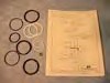 |
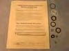
NDI Strut Seal Kit
This kit contains all the seals used in a single strut assembly for the Glasair II RG and III’s. This installation will work for either main gear or nose gear struts and comes complete with instructions. It is a good package to keep handy should the need arise. |
Part No: 342-5110-501 |
| New Style Piston with Seals – Upgrade
Kit owners who are rebuilding hydraulic actuators or are experiencing rapid leak down of hydraulic pressure may wish to upgrade the actuator cylinder with the latest design piston. NOTE: A rapid leak down of hydraulic pressure may also be due to debris or a damaged seal in the pump, such as the emergency extension valve “O” rings on early style hydraulic pumps. |
Part No: 342-5624-104 |
|
551-0345-001
330-0340-001
331-0330-006 |
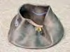
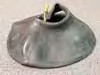
Fuel Cap
This is a very well designed machined aluminum cap with a Viton rubber gasket (unaffected by fuel). Improved over the early Glasair I fuel caps for ease of removal. This cap fits into a notched sleeve and then is rotated against a positive stop and locked with a cam lever. Note: Glasair II and III kits come supplied with two fuel caps and related hardware for the main wing tank and one fuel cap and related material for the header tank. Most Glasair I kits were supplied with one fuel cap. |
|
| Fuel Cap | Part No: 331-0330-201 |
|
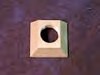
| Fuel Sump. Molded fiberglass fuel sump. | Part No: 302-0165-001 |
|
| Fuel Screen. For fuel sump. | Part No: 330-0340-001 |
|
| Fuel Screen Insert. Bonds to sump for installing finger screen. | Part No: 551-0345-001 |
|
| Fuel Drain. For fuel sump. | Part No: 320-0334-001 |
|
| Fuel Drain Insert. Bonds to sump for installing fuel drain. | Part No: 551-0335-001 |
|
| Fuel Cap Assembly Seal. Made of viton rubber, unaffected by fuel. | Part No: 331-0330-006 |
|
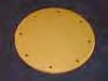 |
Fuel Bay Access Cover Plate
For builders using the capacitance style fuel quantity probes in their main tank instead of the stand pipe fuel gauge, we are supplying a cover plate to close off the hole where the stand pipe would normally be. This removable cover plate provides access for inspection and maintenance of the stainless steel flapper valves and the fuel pick up tube with screen. |
Part No: 552-0421-002 |
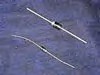
| Pitot Static System Option Kit
The pitot static option kit available for the Glasair I, II, or III aircraft is of conventional aircraft design. It includes sufficient mounting materials to install the pitot tube on either outboard wing inspection panel. The ¼” O.D. tubing provided with the kit comes in two colors to lessen the possibility of incorrect connections to the instruments. The static system includes two fuselage-mounted static ports, an alternate static source which also functions as a low point static system water drain, and sufficient tubing and connectors to install static lines to the airspeed indicator, altimeter, rate of climb indicator, and Transponder altitude encoder |
||
| 14 V Pitot Static System Option Kit | Part No: 121-5812-501 |
|
| 28 V Pitot Static System Option Kit | Part No: 121-5812-502 |
|

120-5812-012 |
Heated Pitot Tube
This 14 V heated pitot tube is a military-spec, “L” shaped AN5812-12 type, which uses 1/4″ AN flared tube fittings. The tube comes with an AN315-1 phenolic connector receptacle |
Part No: 120-5812-012 |
| Static Port Installation
This installation is part of the (above) Pitot Static System but is designed for those builders who already have an existing two tube pitot head and want to incorporate an improved system for airspeed accuracy. Working cooperatively with builders in the field we found a suitable fuselage location. This fuselage static port was incorporated in our flying Glasair III and we were pleased with the increased accuracy of our airspeed numbers, particularly in the upper speed range. Retrofitting (or new installation) of this fuselage static source can be done very easily. Glasair Aviation, LLC has a small aluminum static port (about the size of a quarter) which is installed onto the fuselage skin of the aircraft. Included with this static port kit is ¼” OD blue nylon tubing (to denote static lines), connectors, instructions, and a combination cockpit alternate static source/low point drain. |
Part No: 121-1501-501 |
|
800-0660-001 |
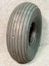
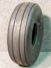
Tires and Tubes McCreary 5 x 5:00 tires, six ply rating, nylon cord. Fits main gear on all Glasair TD and FT models. Glasair TD and FT |
Part No: 800-0660-001 |
800-0660-002
800-0660-003
800-0675-001 |
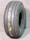
Goodyear 5 x 5:00 tries, six ply rating, nylon cord. Replacement main gear tires for Glasair I and II RG models. Required for II, II-S, and Super II-s RG’s using slotted flaps due to their lower profile (clearance to flap push rods).
Model Glasair I/II RG/II/II-S |
Part No: 800-0660-003 |
| Goodyear 5 x 5:00 tries, 10 ply rating, main gear tires for Glasair III. | Part No: 800-0660-002 |
|
| Tubes for all models TD/FT/RG and III main gear. | Part No: 800-0675-001 |
|
800-0670-001 |
Lamb Tire / Tube
11.4 x 5.00 tire, fits both RG and FT nose gear, eight ply rating, nylon cord. Included in all kits except TDs. |
|
| Tire | Part No: 800-0655-001 |
|
| Tube | Part No: 800-0670-001 |
|
| Tail Wheel
Tail wheel for Glasair TD. Flexible solid rubber. Included in Glasair TD kits. |
Part No: 800-0600-001 |
|
| Brake Lining Kit
Replacement brake linings for Cleveland brakes. Since all Glasair models use differential braking to assist in directional control, it is important to replace the linings before they are worn excessively. Excessively worn linings may allow the O-ring on the brake piston to move past its seal in the caliper, resulting in loss of fluid pressure and immediate brake failure, not to mention the damaged discs. For a number of years Cleveland offered standard organic and heavy duty asbestos brake linings for their wheels and brakes. In January 1988 the two types of linings were discontinued and a single, improved brake lining was introduced. The prices are higher than the older types of linings but performance and durability are greatly improved. Kit includes 2 lings and riits (enough for one wheel). |
||
| Model: Glasair I/II | Part No: 900-0678-501 |
|
| Model: Glasair III | Part No: 900-0678-502 |
|
 |
Replacement Grove Brake Master Cylinder
Model: All RG & Super II Models |
Part No: 900-0397-001 |
Electrical Options & Accessories
| Lighted Panel Switches
Manufactured by Microswitch, these panel switches are an enhancement to any instrument panel. These are a flush mounted lighted rocker switch that illuminates an opaque white cap when you press it to the “on” position. The white caps can easily be labeled for quick cockpit reference. The switch bracket is able to house (1) master switch and (7) rocker switches. Installation is quick and simple. These are the same Panel Switches that are installed in the Glasair Super II-S prototype. Order early as stock quantities are limited. |
|
| Switch Bracket (One Needed) | Part No: 210-0061-008 |
| Switch-Cap (Up to 7 req.) | Part No: 210-0054-010 |
| Switch-Lamp 14 V (Up to 7 req.) | Part No: 210-0073-001 |
| Switch-Lamp 28 V (Up to 7 req.) | Part No: 210-0085-001 |
| 14 Volt High Intensity | Part No: 210-0070-001 |
| 28 Volt High Intensity | Part No: 210-0017-001 |
| Master Switch (One Needed) | Part No: 210-0034-001 |
| Complete Eight-Switch Installation – 14 Volt | Part No: 210-0061-501 |
|
Wire Marking System This is an excellent wire marking system, as used on the Glasair III prototype. The system consists of a booklet of tabs that can be marked with a code number, peeled off, and then wrapped around the wire. |
Part No: 870-0014-101 |
| Strobe & Lighting Packages
In order to simplify the ordering of strobe and light packages, Glasair Aviation, LLC has put together the following packages. You may order the whole nav and strobe requirements using this method, or choose the system that you desire and purchase the individual kits as needed. When specifying the package, realize that our invoice will indicate the individual kits within the package and not the package itself. Part numbers given are 14 volt and are later model Glasair configuration. Please reference individual packages for 28 volt part numbers or Glasair I configuration if applicable. NOTE: If you order by the package system, and you already have the strobe wire harnesses or the clear wing tip lenses, please specify this, or if there is any alteration from the packages listed below. |
|
| PACKAGE A – ANTICOLLISION STROBE PACKAGE
Anticollision strobes (part number 221-0460-501) are mounted on the outside of the wing tips, nav lamps (part number 221-0419-501) in the colored wing tip lenses and a standard tail light kit (part number 212-0599-501). Two strobe light wire harnesses (part number 210-0417-120) are also needed. |
|
| PACKAGE B – NAV STROBE COMBO PACKAGE
The nave strobe combo package is designed for those who want the cleanest installation. The nav strobe combo kit (part number 211-0421-501) is installed in clear wing tips (part number 672- 0376-003/004). This gives strobe and nav lamp requirements for the front of the airframe. The nav strobe tail light (part number 212-0601-501) is needed for the strobe/nav requirements for the rear of the airframe. Two strobe light wire harnesses (part number 210-0417-120) are also needed. |
|
| PACKAGE C – NAVIGATION STROBE LIGHT PACKAGE (GLASAIR I ONLY)
This package has the strobes, nav lights and tail lights all in one unit (part number 211-0420-501). Mounted on the outside of the wing tips, it gives full coverage of the airframe for all requirements. Easiest to install, but also the most drag. It is not a good installation for the Glasair II, II-S, Super II or III kits because the Hoerner wing tips supplied with the kit have cutouts for the nav lens already molded into the parts. Two strobe light wire harnesses (part number 210-0417-120) are also needed. |
|
| Anticollision Strobe Light Kit
This kit includes a Whelen model A413-A power supply, two A-612 magnifying lenses, two A-610 flash tube assemblies, and installation instructions. The magnifying lenses are simply mounted with silicone in holes cut in the Glasair wing tips. Navigation and tail lights must be used with this system to satisfy FAR requirements for night flight. Weight: 3.75 lb. |
|
| Anticollision Strobe Light Kit – 14v | Part No: 211-0460-501 |
| Anticollision Strobe Light Kit – 28v | Part No: 211-0460-502 |
|
Glasair II/III Wing Tip Extension Anticollision Strobe Light Kit This kit includes the magnifying lenses, flash tube assemblies, and wire connectors for installing strobe lights in the wing tip extensions. This kit assumes a power supply and wiring in the wings has been previously installed for standard (short) wing tip strobe lights. |
Part No: 212-0687-501 |
| NAV/Strobe Combo Kit
This kit includes a Whelen A413-A power supply, two A650PG/PR-14 or –28 wing tip combination navigation- strobe light assemblies, 18 gauge 2-conductor wire connectors for the navigation lamps, and installation instructions. This kit enables the strobe and nav lights to be installed in a clear wing tip lens. It eliminates the strobe lights from being on the outside of the wing. Clear lenses and a Nav/Strobe Tail Light Installation are required for this installation to work. This installation differs from the Navigation/Strobe Light Kit in that it does not include the tail light in the fixture. |
Part No: 211-0421-501 |
| NAV/Strobe Combo Wing Tip Extension Installation
This kit includes the A650PG lights and related parts and wire to install the Nav/Strobe Combo installation into your extended wing tips. Note that clear lenses are required for this installation and it assumes that you have already purchased the Nav/Strobe Combo Installation for the standard wing tips. If you are only installing the Extended Wing Tips you will need to purchase the Nav/Strobe Combo Kit listed above. |
Part No: 211-0425-501 |
| Strobe Light Wire Harness
This is the Whelen strobe wire assembly for any of the strobe light systems. It includes one 20 foot shielded strobe wire assembly with quick disconnects for installation between the strobe power supply and the flash tube assembly in the wing tips. Sold separately so the wiring can be installed before closing the wing. Two of these units are required for each airplane. Weight: 1 lb. |
Part No: 210-0417-120 |
| Navigation / Strobe Light Kit
This kit includes a Whelen A413-A power supply, two A- 600 PG/PR wing tip combination navigation-strobe light assemblies, 18 gauge 2-conductor wire and connectors for the navigation lamps, and installation instructions. When mounted to both wing tips, this system satisfies all FAR requirements. Each lighting assembly incorporates a colored navigation light, a strobe light, and a white tail light. This system produces slightly more drag in flight, but saves construction time for Glasair I’s since the standard flush-fit lenses, provided with later model Glasair I kits, do not have to be installed. The Strobe Light Wire Harness kit will be needed to complete this installation. Weight: 4-1/2 lb. NOTE: This kit is designed as a time saver for Glasair I Builders with earlier model wing tips. Glasair II and III Builders please refer to Anticollision Strobe Light Kit and Navigation Lamp Kit or Nav/Strobe Combo Kit for proper installation. |
Part No: 211-0420-501 |
| Navigation Lamp Kit – Glasair II/III
This kit designed for the Glasair II/III kits includes Grimes navigation lamps, lamp sockets with brackets, butt connectors, blade terminals, ring terminals, 4o ft. of 18 gauge 2-conductor wiring with quick disconnects, and detailed installation instructions. These lamps satisfy FAR night flying intensity requirements. This kit is designed to be used with the standard Glasair II/III Hoerner wing tip lenses. Weight: 1-1/3 lb. |
|
| Navigation Lamp Kit – 14v | Part No: 211-0419-501 |
| Navigation Lamp Kit – 28v | Part No: 211-0419-502 |
| Navigation Lamp Kit (Glasair I)
This kit is the same as the one mentioned above but includes GE tail lamps, sockets and installation hardware for aft wing tip mounted tail lights as is used on Glasair I’s. |
Part No: 211-0420-502 |
|
| Wing Tip Extension NAV Lamp Kit – Glasair II/III
This kit provides the lamps, sockets, wire, and connectors to install NAV lamps in your Glasair II or III wing tip extensions. The wing tip extension NAV lights connect to wiring already installed in the wing for the standard short tip NAV lights. This kit assumes that the wiring is already installed in the wing from the standard Nav Light Kit. |
||
| 14V | Part No: 212-0686-501 |
|
| 28V | Part No: 212-0686-502 |
|
| Tail Light Kit
This tail light kit is designed for installation on the premolded rudder tail light mounting pad on all Glasair II and III kits. Includes tail light assembly, mounting hardware, all necessary wiring and electrical connectors, and installation instructions. Weight: 2 oz. Glasair I builders may install this tail light assembly on their rudders by fabricating a faired-in mounting base from foam and fiberglass. CAUTION: Glasair I’s may require additional weight in the counterweight to keep the rudder assembly properly balanced. Refer to Appendix E of your Glasair Instruction Manuals for counterweight calculation procedures. |
||
| 14V | Part No: 212-0599-501 |
|
| 28V | Part No: 213-0599-501 |
|
| NAV/Strobe Tail Light Installation
When the wing tip strobe lights are installed inside the wing tip lenses, this unit is needed to meet FAR requirements. The installation includes the Whelen combination strobe light/tail light assembly, wire harness and connectors. The same power supply installed for the wing tip strobe lights will also power this unit. |
||
| 14 – V | Part No: 212-0601-501 |
|
| 28 – V | Part No: 213-0601-501 |
|
| Lamps | ||

210-0359-001/4 |
Navigation Lamp, 14 V | Part No: 210-0359-001 |
| Navigation Lamp, 28 V | Part No: 210-0359-004 |
|
| Tail Lamp, Glasair I, 14 V | Part No: 210-0359-002 |
|
| Tail Lamp, Glasair II, III 14 V | Part No: 210-0508-014 |
|
| Tail Lamp Glasair II, III 28 V | Part No: 210-0508-028 |
|
210-0359-003/5 |
14 Volt Landing Light | Part No: 210-0359-003 |
| 28 Volt Landing Light | Part No: 210-0359-005 |
|
 |
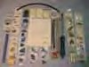
Electrical Kit
This time-saving kit is designed to meet electrical system requirements for the Glasair. If purchased separately, this item would run 33% more. This kit not only saves you money but also saves you the time that would be spent locating and purchasing the kit items individually. We would be glad to mail you a parts list if you desire to review this option. The kit includes: angle aluminum; battery solenoid; starter solenoid; avionics solenoid; 17 ft. #4 wire; 12 ft. #8 wire; 2 ft. #10 wire; 60 ft. #16 wire; 280 ft. #18 wire; 280 ft. #20-2 wire shielded 1.5 amp diodes; row of 40 terminal blocks; all necessary sire crimp-on terminals; 3 sizes of spiral wrap for wire protection and bundling (75 ft. total); 10 ft. high temp spiral wrap 4 sizes of heat shrink tube (7 ft. total); 200 small cable ties; 100 large cable ties; 50 x-large cable ties; 70 assorted nylon clamps, screws, and adhesive backed anchor pads for wire routing. Wiring supplied by Glasair Aviation, LLC is aircraft quality wiring. This more costly wire also has the advantage of not producing toxic fumes in the event of fire. NOTE: 28 volt system is slightly different in quantity and parts |
|
| 14V | Part No: 211-0229-501 |
|
| 28V | Part No: 211-0229-502 |
|
 |
Ground Bus Bar
These high quality Cole Hersey Bus Bars provide common terminal points for the positive and negative leads of electrical components in your Glasair. Two needed per plane. |
Part No: 210-0448-001 |
| Antennas
These lightweight, double-element dipole antennas are designed for installation on the inside of fiberglass aircraft structures. They consist of self-adhesive copper foil tape trimmed to the proper length for tuning and solderred to double-shielded tri-axial cable with ferrite matching cores. Easy to install, these are used exclusively on all of our factory aircraft with excellent results and zero airframe drag! Kits include the pre-soldered antenna and cable assembly, a male BNC connector and instructions (Note: With the tri-axial cable shortened appropriately, this antenna can also be mounted on the fuselage sidewall behind the baggage bulkhead as a secondary COM antenna.) |
||
| Com (118-1326 Mhz), vertical fin mounting Triax cable length 275″ | Part No: 211-0112-501 |
|
| NAV/VOR (108-118 MHz) | Part No: 211-0112-502 |
|
| MKR (75 MHz) triax cable length 161″ | Part No: 211-0112-503 |
|
| FM entertainment (88-108 MHz) Triax cable length 148″ | Part No: 211-0112-504 |
|
| Antenna – Transponder | Part No: 211-0112-507 |
|
| Individual Electrical Components
Following is a list of electrical components available for builders who are working on the electrical system installation in their Glasairs. Other electrical system components, such as replacements for components included with the retractable gear kits, are also available. Call our parts order desk if what you need is not listed. |
||
 |
Master Switch, Dual (need cover) | Part No: 210-1994-011 |
| Master Switch Cover | Part No: 210-1843-001 |
|
| Control Stick Grip Momentary Switch
These switches are specifically for use in our Glasair stick grips. They are of excellent quality and meet or exceed aviation mil-spec. Not useful for autopilot release. |
Part No: 620-1111-001 |
|
| Autopilot Switch | Part No: 620-1212-001 |
|
 |
Elevator Trim Hat Switch
This handy four way aviation mil-spec switch mounts easily on the Glasair Military stick grip for use with the elevator trim system. It is conveniently marked for easy visual reference. Used for both pitch and roll. |
Part No: 210-0098-001 |
 |
Solenoids | |
| Solenoid, Cont. Duty, 14 – V | Part No: 210-0024-059 |
|
| Solenoid, Cont. Duty 28 – V | Part No: 210-0024-063 |
|
| Microswitches (each solenoid requires a 1.5 amp diode) | ||
| Microswitch, 1XE1 | Part No: 210-0100-001 |
|
| Microswitch, 411SM1H4 w/actuator | Part No: 210-0411-004 |
|
 |
Circuit Breakers | |
| Circuit Breaker, 2 Amp, Klixon | Part No: 210-0200-002 |
|
| Circuit Breaker, 3 Amp, Klixon | Part No: 210-0200-003 |
|
| Circuit Breaker, 4 Amp, Klixon | Part No: 210-0200-004 |
|
| Circuit Breaker, 5 Amp, Klixon | Part No: 210-0200-005 |
|
| Circuit Breaker, 7.5 Amp, Klixon | Part No: 210-0200-007 |
|
| Circuit Breaker, 10 Amp, Klixon | Part No: 210-0200-010 |
|
| Circuit Breaker, 15 Amp, Klixon | Part No: 210-0200-015 |
|
| Circuit Breaker, 25 Amp, E-T-A | Part No: 210-0200-025 |
|
| Circuit Breaker, 40 Amp, E-T-A | Part No: 210-0200-040 |
|
| Circuit Breaker, 60 Amp, E-T-A | Part No: 210-0200-060 |
|
 |
Diodes | |
| 400 PIV 1.5 AMP | Part No: 210-5395-015 |
|
| IN 5400 3.0 AMP | Part No: 210-5400-001 |
|
| AMP Connectors | ||
| AMP Connector, Male, 3 Pin, w/Pins | Part No: 210-0441-001 |
|
| AMP Connector, Female, 3 Socket, w/Pins | Part No: 210-0442-001 |
|
| AMP Connector, Male, 2 Pin | Part No: 210-1022-003 |
|
| Pins for above | Part No: 210-2103-002 |
|
| AMP Connector, Female, 2 Socket | Part No: 210-2022-003 |
|
|
Pins for above |
Part No: 210-1103-002 |
|
| Wire | ||
| Coaxial Cable, Antenna | Part No: 870-0058-001 |
|
| Triaxial Cable, Antenna | Part No: 870-0058-002 |
|
| Wire, 2 Ga., Single Conductor | Part No: 870-0228-002 |
|
| Wire, 4 Ga., Single Conductor | Part No: 870-0228-004 |
|
| Wire, 8 Ga., Single Conductor | Part No: 870-0228-008 |
|
| Wire, 10 Ga., Single Conductor | Part No: 870-0228-010 |
|
| Wire, 14 Ga., Single Conductor | Part No: 870-0228-014 |
|
| Wire, 16 Ga., Single Conductor | Part No: 870-0228-016 |
|
| Wire, 18 Ga., Single Conductor | Part No: 870-0228-018 |
|
| Wire, 20 Ga., Single Conductor | Part No: 870-0228-020 |
|
| Wire, 22 Ga., Single Conductor | Part No: 870-0228-022 |
|
| Wire, 24 Ga., Single Conductor | Part No: 870-0228-024 |
|
| Wire, 16 Ga., 2 Cond., Shielded | Part No: 870-0228-162 |
|
| Wire, 18 Ga., 2 Conductor | Part No: 870-0228-182 |
|
| Wire, 20 Ga., 2 Cond., Shielded | Part No: 870-0228-202 |
|
| Wire, 20 Ga., 2 Conductor | Part No: 870-0228-212 |
|
| Wire, 20 Ga., 3 Conductor | Part No: 870-0228-203 |
|
| Adhesive Mounting Base used for attaching wire to surface | Part No: 210-0345-001 |
|
| Terminal Blocks | ||
| Terminal Block Track | Part No: 210-6018-051 |
|
| Terminal Block Assembly | Part No: 210-6041-011 |
|
| Terminal Block End Stop | Part No: 210-6041-111 |
|
 |
Spiral Wrap | |
| ¼” Spiral Wrap | Part No: 830-0598-001 |
|
| 3/8″ Spiral Wrap | Part No: 830-0598-002 |
|
| ½” Spiral Wrap | Part No: 830-0598-003 |
|
 |
High Temperature Spiral Wrap | |
| 1/8″ High Temperature | Part No: 830-0125-001 |
|
| ¼” High Temperature | Part No: 830-0250-001 |
|
| 3/8″ High Temperature | Part No: 830-0375-001 |
|
| ½” High Temperature | Part No: 830-0500-001 |
|
 |
Heat-Shrinking Tubing
Seal and insulate splices and terminal connections like the pros do. Black color. Prices are per foot. |
|
| 1/8″ | Part No: 830-0352-001 | |
| 3/16″ | Part No: 830-0352-002 | |
| 1/4″” | Part No: 830-0352-004 | |
| 3/8″ | Part No: 830-0352-003 | |
| Squat Switch Retrofit Kit
The optional squat switch is designed to prevent inadvertent gear retraction while the aircraft is on the ground. Mounted on the right main gear strut, this switch could save an embarrassing and costly mistake. Kit includes microswitch, mounting scissor pin assembly, wire, instructions and related hardware. Included as standard equipment in Glasair III kits. |
Part No: 352-5110-501 |
| Electric Trim GII/III
The electric trim option kit is designed to replace the manual trim wheel unit in the Glasair II, II-S, Super II-S, and III aircraft. The hat switch (not included in this installation) is mounted on the military control stick grip (Part No: |
|
| Electric Trim-II/III 14V | Part No: 212-0242-501 |
| Electric Trim-II/III 28V | Part No: 213-0242-501 |
| Electric Trim (Glasair I)
This kit is the same as the one listed above but is expanded to fit the Glasair I series by including the cables, trim springs and slight modification to kits supplied in the elevator trim upgrade kit currently available, does not include actuator. |
Part No: 211-0242-501 |
| Electric Flap
This custom/simple installation uses a jackscrew which mechanically free wheels at its travel limit eliminating the need for limit switches and gives infinite positioning possibilities. This will also increase the standard flap travel from the existing 34 degrees to approximately 50 degrees for increased drag, as well as eliminating the flap handle in the cockpit. Installation comes complete with all materials needed and detailed instructions. Note: This installation is required with the Slotted Flap Installation. |
|
| Glasair II/II-S/Super II-S/III – 14V | Part No: 212-3670-501 |
| Glasair III 28V | Part No: 213-3670-501 |
Tools & Supplies
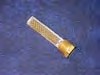
| Bidirectional Cloth
Standard bi-directional weave used in Glasair and supplied with kit. Style 7781. 9 oz. per square yard. 50″ width. (10 ft. minimum order). Note: This cloth is chemically treated (chemical sizing) specifically for vinylester resin to achieve maximum strength. |
Part No: 270-0110-002 |
|
| Peel Ply
This 60 inch wide Peel Ply is a Nylon Cloth which resin will not adhere to. It is used for both cosmetic finishing and also to leave a laminate with a clean, rough surface ready for bonding. Note Newsletter 23 for specific application. Minimum order is 5 feet |
Part No: 270-0500-102 |
|
 |
Milled Fibers
Chopped fiberglass strands used for structural bonding and filling when mixed with resin. 250 gram package. |
Part No: 270-0130-001 |
| Q-Cells
Quartz microspheres uses as a lightweight filler when mixed with resin, not to be used for structural bonding. 200 gram package. |
Part No: 270-0140-001 |
 |
Cabosil
Finely ground glass powder used as a filler in resin mixtures not to be used for structural bonding. However, small amounts added to mill fiber/resin mixture will help to smooth it out. 100 gram package. |
Part No: 270-0131-002 |
| Partall Film #10
PVA release agent, used primarily as a mold release agent (water soluble). Also used as an aid for surface curing of resins and gelcoat by sealing it from oxygen. 16 oz. bottle. |
Part No: 270-0145-101 |
|
 |
Vinylester Resin – 411-45
This resin is NOT promoted and does NOT include promoters or MEKP catalyst. Thus, at the time or ordering, please specify if chemicals are needed. (See below). Estimated 6 month shelf life. (1 gallon minimum order). NOTE: Hazardous material shipping charges apply for international orders. Domestic orders for this product can only ship ground, but have no hazardous material shipping charges. Call for more information! |
Part No: 270-0155-301 |
 |
Vinylester Fire Retardant Resin – 510C350 (1 quart)
Will not support a flame once the ignition source has been removed. Specified for Glasair III induction system fabrication. This resin is NOT promoted and does NOT include promoters or MEKP catalyst. Thus, at the time or ordering, please specify if chemicals are needed. (See below). Use same catalyst (MEKP) as standard 411-45 vinylester resin. Estimated 1 to 2 month shelf life. (1 quart minimum order). NOTE: Hazardous material shipping charges apply for international orders. Domestic orders for this product can only ship ground, but have no hazardous material shipping charges. Call for more information! |
Part No: 270-0155-108 |
| Gelcoat (1 quart)
Ferro white polyester gelcoat. Used to finish the seam areas on the Glasair and Glastar airframe. Thin with acetone for spraying and catalyze with MEKP. (32 oz. minimum order). Estimated 3 month shelf life. NOTE: Hazardous material shipping charges apply for international orders. Domestic orders for this product can only ship ground, but have no hazardous material shipping charges. Call for more information! |
Part No: 270-0129-103 |
|
| Cobalt Promoter (1 oz. Boxed UPS)
NOTE: Hazardous material shipping charges apply for international orders. Domestic orders for this product can only ship ground, but have no hazardous material shipping charges. Call for more information! |
Part No: 270-0135-101 |
|
 |
DMA Accelerator (1 oz. Boxed UPS)
NOTE: Hazardous material shipping charges apply for international orders. Domestic orders for this product can only ship ground, but have no hazardous material shipping charges. Call for more information! |
Part No: 270-0135-201 |
| MEKP Catalyst (4 oz. Boxed UPS) | Part No: 270-0105-101 |
| NOTE: Hazardous material shipping charges apply for international orders. Domestic orders for this product can only ship ground, but have no hazardous material shipping charges. Call for more information! | ||
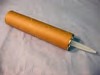 |
Empty Caulking Tubes
These empty caulking tubes are a great time saver and can significantly reduce the preparation and construction time of certain jobs (such as closing the wing). They come in real handy when dispensing Milled Fibers, Q-Cells and Cabosil mixtures. |
Part No: 270-0103-001 |
 |
Resin Mixing Sticks
¾” x 6″ wooden sticks. Use for mixing resin, shimmying, etc. The uses are limited only by your imagination. Box of 500. |
Part No: 270-0180-101 |
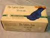 |
Surgical Gloves
Tight fitting latex gloves for hand protection from the chemicals (resin, catalyst, acetone, etc.) used in composite construction. Box of 100 gloves (fit either hand). One size fits all. |
Part No: 270-0230-001 |
 |
Resin Brushes
Laminator’s bristle brushes, with wooden handle. This is the number 1 tool for constructing a fiberglass airplane. Don’t run short! |
|
| Resin Brushes – 1″ Size | Part No: 270-0185-001 |
|
| Resin Brushes – 2″ Size | Part No: 270-0185-002 |
|
| Box of 36, 1″ Size | Part No: 270-0185-101 |
|
| Box of 24, 2″ Size | Part No: 270-0185-102 |
|
 |
Resin Mini-Pump
The Resin Mini Pump screws directly onto a gallon container (just like the one supplied by Glasair Aviation, LLC for one gallon resin shipments) and gives out about 35 grams of resin per pump. They come in a set of two so you can either keep one as a spare or use it for acetone. |
Part No: 270-0172-101 |
 |
Syringe (5 pack)
5.0 ml. all plastic syringe. Molded polypropylene piston will not dissolve in MEKP as most rubbers will. Calibrated in 0.1 ml. increments. Accurately measures catalyst; helps prevent skin contact with catalyst. Needles not included and not needed for measuring catalyst. |
Part No: 270-0190-001 |
 |
Squeeze Bottle (Mekp Dispenser)
This handy squeeze bottle dispenses MEKP catalyst by the drop for small resin batches. Supplied with a chart calibrated in the number of drops required for different sized resin batches catalyzed at different rates. This is a very easy and accurate method of dispensing catalyst and avoids the dangers of skin contact and accidental eye contamination. (See “Glasair News” #16 for a further description). |
|
 |
Mold Release Wax
Use for fabricating procured laminates on an aluminum sheet or for any application where parts are formed using a mold and then separated after curing. 14 oz. can. |
Part No: 270-0205-001 |
 |
Ultralite Body Filler
1 qt. |
Part No: 270-0200-001 |
| Ultralite Body Filler
1 gal. |
Part No: 270-0200-002 |
|
| Vinyl Masking Tape
½” wide vinyl tape which we have found works ideally for masking trim stripe details when painting. Forms beautiful inside and outside tight radius curves without dimpling. Does not allow paint-bleed through on the edges as do most masking tapes. Pulls easily without damaging paint underneath. You’ll love working with this tape |
||
| Masking Tape – ½” Roll | Part No: 270-0195-002 |
|
| Masking Tape – ½” Roll (Doz.) | Part No: 270-0195-102 |
|
| Masking Tape – ¾” Roll | Part No: 270-0195-001 |
|
| Masking Tape – ¾” Roll (Doz.) | Part No: 270-0195-101 |
|
| Rotary Cloth Cutter
This “pizza wheel” style cloth cutter cuts neatly and cleanly on a wooden or plastic-surfaced bench or table. Works great for making curved cuts in fiberglass cloth. Reduces fraying and helps prevent stretching of the cloth. The blade is made of sharp tungsten steel, and one extra blade is included with the cutter kit. |
||
|
Rotary cloth cutter |
Part No: 810-0215-501 | |
|
Replacement blade for rotary cutter |
Part No: 810-0215-001 | |
 |
CherryMax Flush-Head Blind Rivets
Let’s be frank: there are a handful of holes along the forward wing spar in the area of the strut beam that are a bear to rivet with standard, driven rivets. Although it is possible to buck all these rivets, many builders have inquired about the possibility of using blind rivets in these locations. That’s perfectly fine, as long as the rivets are equally as strong as regular AN426AD4’s, and only CherryMax rivets meet that criterion, These CR3212-4-8 rivets are just the right size for riveting the skins to the forward spar. |
Part No: CR3212-4-8 |
 |
Torque Seal
This colorful paste is primarily an inspection aid device. The seal paste is placed between two objects (example, the nut on a bolt) that we want to make sure are not moving relative to each other. If the seal is broken, movement has taken place and further action should be taken. Also great for indicating completion or final torque. The set includes five colors (pink, green, blue, yellow and orange). Use one color for gear up hydraulics, one for gear down and so on. |
Part No: 620-0642-501 |
Safety Equipment
 |
ACR Aerofix 406 PLB w/GPS
Description: The most advanced Personal Locator Beacon on the market, the AeroFix 406 GPS I/O PLB includes an internal GPS, exclusive FastACQ™ GPS relay technology and an external GPS optical interface, giving you, the user, unparalleled versatility. Features Internal GPS acquires your coordinates when the unit is activated and transmits your exact location to within 110 yards to local rescue agencies ACR Electronic’s FastACQ™ technology relays accurate GPS information to the satellites faster than all other internal GPS PLB’s PLB technology transmits signals that are monitored by NOAA (National Oceanic and Atmospheric Administration) and AFRCC (Air Force Rescue Coordination Center) Each unit contains and transmits a 15-digit Unique Identifying Number (UIN) which is picked up by satellites and provides rescuers with your name, address and other pertinent information Transmits two signals: 406 MHz via COSPAS-SARSAT satellite system and on 121.5 MHz (SAR homing frequency) The 406 MHz signal allows rescuers to locate your position within a 2 mile radius, while the 121.5 MHz signal allows rescuers to home in to pinpoint your position External GPS optical interface (NMEA 0183) allows you to download your GPS coordinates from your hand-held GPS unit into your PLB When activated, your GPS coordinates will be automatically included in your emergency transmission to satellites – saving valuable time for your distress message to reach local rescue centers The flat, stainless steel antenna wraps compactly around bottom case for easy stowage and is easily positioned when needed Functional test switch for battery power and 406 MHz transmission The unit floats to avoid loss if dropped in water and is waterproof to 3.3 feet Removable holster provides functionality, style and protection for your PLB Specifications Weight: 12 ounces Dimensions: 1.74 x 5.71 x 3.03 inches Material: Glass reinforced polycarbonate blend Deployment: Manual Frequency: 406.038 MHz, 121.5 MHz Battery type: Lithium Radiating Power: 5 watts ± 2dB (406.025 MHz) 50 mW ± 3dB (121.5 MHz) Operational Life: In excess of 24 hours @ -40°C (-40°F), longer in higher ambient temperature Made in USA |
|
| ACR Aerofix 406 PLB w/GPS
ACR Part No: 2799.4 |
Part No: 014-02231-01 |
|
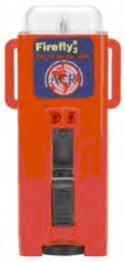 |
FireFly3 Strobe Light
Features: Manually activated rescue strobe 360° high intensity Xenon strobe visible for up to 2 miles Large sliding switch allows for easy operation by gloved hands Newly-designed base platform allows unit to stand upright easily Conceived as state-of-the-art replacement for famous Firefly forerunners, 4F and 4G Designed as “electronic flare” to replace day/night pyrotechnic signal in aviation life rafts Stainless steel retainer securely attaches removable battery door to case Integral strapping slots provide a secure anchor point Ideal for life vests, safety harnesses, backpacks and flight suits. Common Specifications for FireFly3® Size: 4.75 x 2.2 x 1.2 in (12.1 x 5.6 x 3.0 cm) Weight: 3.8 oz (105 g) with Lithium batteries Material: Polycarbonate Waterproof: Factory tested to 10 m (33 ft) Beam Angle: Omni-directional 360° Visibility: Visible up to 2 mi (5 km) Flash Rate: 60 ± 10 flashes per minute Lamp: High intensity Xenon strobe Battery Type: 2 “AA” alkaline or 1.5V lithium (5 year replacement life) not included Certification: USCG 161.012/58/0 (alkaline or lithium) USCG SOLAS 161.112/58/0; MO LSA Code Res. MSC.81(70); FAA (TSO-C85) approved (with lithium dated batteries only) Limited Warranty: 1 year Operational Life: Minimum 8 hours continuous @ -1°C meets USCG and IMO (SOLAS) specifications. |
|
| FireFly3 Strobe Light
ACR Part No: 3995.3 |
Part No: 014-02232-01 |
|
 |
HotShot Signal Mirror w/Whistle
ACR Part #: 1700 Our Part #: 014-02233-01 Customer Price: call for price Sighted signaling mirror with float and whistle Designed to provide optimum sighting “spot” with holographic red dot viewing window When target image, mirror and sun are in proper alignment, red dot on target ensures mirror reflection is on target Telescope quality second surface reflective mirror is bright, provides focused image Buoyant float for easy recovery if dropped overboard Patented whistle (meets USCG) for audible alerting in low visibility conditions Lanyard for securing to person or life-raft Simple, total safety signaling package Size: 4.25 x 2.75 x .19 in. (10.8 x 7.0 W x .5 cm) Weight: 1.8 oz (51 g) |
|
| HotShot Signal Mirror w/Whistle
ACR Part No: 1700 |
Part No: 014-02233-01 |
|
Miscellaneous
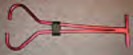 |
Towbars
Handle your Glasair on the ground as easily as it handles in the air with our custom towbar! Made of strong but lightweight aluminum tubing and anodized bright red for high visibility, the tow bar can easily be carried in the baggage compartment and is easy to engage and disengage with a sliding nylon sleeve to lock in place. |
|
| RG Towbar | Part No: 471-0644-301 |
|
| FT Towbar | Part No: 471-0645-101 |
| Jack Stand Kit
This custom jack stand kit comes with two sturdy, tripod style jack stands and two fiberglass jack pads custom-molded to fit the Glasair wing. Jack pads bolt into the tie-down holes and support the wing under the spar. Easy to use screw-jack style jack stands come with long crank handles so you don’t have to be under the wing while jacking. Jack stands’ height adjusts from 23″ to 38″. Capacity: 1 ton per jack. Exclusive fold-up feature for easy storage. Indispensable for RG builders to check the gear retraction cycle and the gear door fit, as well as for periodic maintenance and inspections. (A retraction test should be performed at least at every annual condition inspection). |
Part No: 381-0362-501 |
|
 |
Glasair – Decals
3″ x 18″ Black Glasair logo on clear backing. Pressure sensitive adhesive. For use as an attractive identifying logo on your Glasair in conjunction with your paint scheme. |
Part No: 621-0225-001 |
| 3″ x 18″ black Glasair logo on white backing. Pressure sensitive adhesive for use as a bumper sticker. | Part No: 621-0225-002 |
|
| “100LL Only” fuel filler decal
1-7/8″ x 3-7/8″, silver and black |
Part No: 620-0215-004 |


Nice!!
Br Ralph SE-XVD Sweden
I am in need of a lens cover for the left extended wing tip for my Glasair III Part # 673-0377-003
New or used
Tom Hempstead email: hempstead1944@yahoo.com Phone: 800-574-4447
Pinehurst, North Carolina.
Tom, check with AdvancedAero: https://advanced-aero.com/