Submitted by Randy Bretton
This method was used to locate the slotted flap hinges and build the flaps on my Super II FT. One advantage of this method is that you can check the movement of the flaps before permanently mounting the hinges on the wing.
Overview:
- Make an extra inspection hole in center wing
- Level areas for nutplates using milled fiber and
- Close the
- Trim the trailing edge of the wing
- Build a detachable trailing edge
- Assemble the hinges
- Attach the hinges to the wing using milled fiber and
- Build the flaps around the hinges
- Close the flaps and place on trailing edge board
- Check movement and drill holes in attach angles and
- Install nutplates through the inspection
There is a good description on Glasair News Web site on how to determine the height of the flaps by Troy Scott. I recommend reading this.
Make an extra inspection hole in center wing bay.
This is necessary if you are going to install the nutplates after you close the wing. All I’ll say here is that I ordered 2 additional aluminum inspection covers from Stoddard Hamilton and built structures similar to the factory made inspection holes.
Level areas for nutplates with milled fiber and resin.
Measure and mark the location of the hinges on the outside of the aft shear web. Also measure and record the position of the lower aft shear web cap. You will need this information later when you drill holes through the attach angles and wing. Cut the nutplates out of stock aluminum. Position the nutplates inside the wing, and level areas beneath the nutplates relative to the lower wing skin using milled fiber and resin. I used a smart level to measure the slope of the bottom wing skin, then I shimmed the nutplates to achieve the same slope. Then wax the plate and level the area with the milled fiber and resin mix. You don’t need to be exact. You can correct the slope later (see installing the nutplates), but closer is better.
On my FT, the unidirectional main gear laminates overlap the area for the inboard nutplate. Don’t level the whole area to the height of the unidirectionals. Make a step and use 2 nutplates. The 2 outboard screws need to be close to the shear web cap (like the others) or the flap push rod will not clear. Level the inboard area over unidirectional laminates.
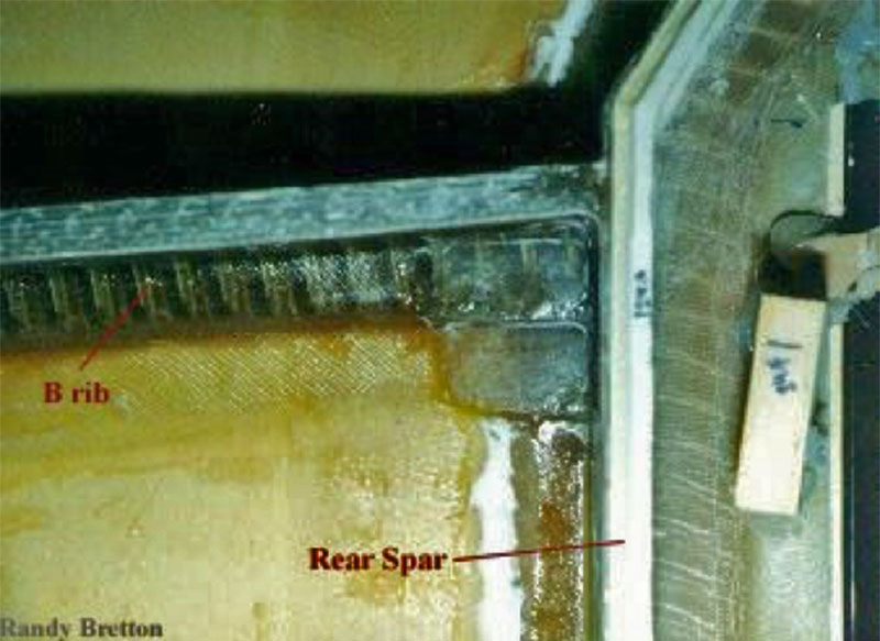
Close the wing, and Trim the trailing edge of the wing.
I’ll let someone else write this one.
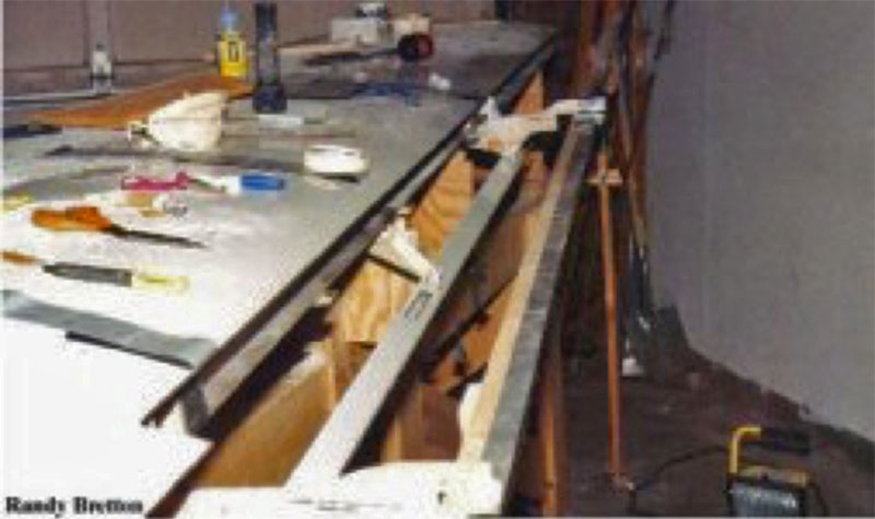
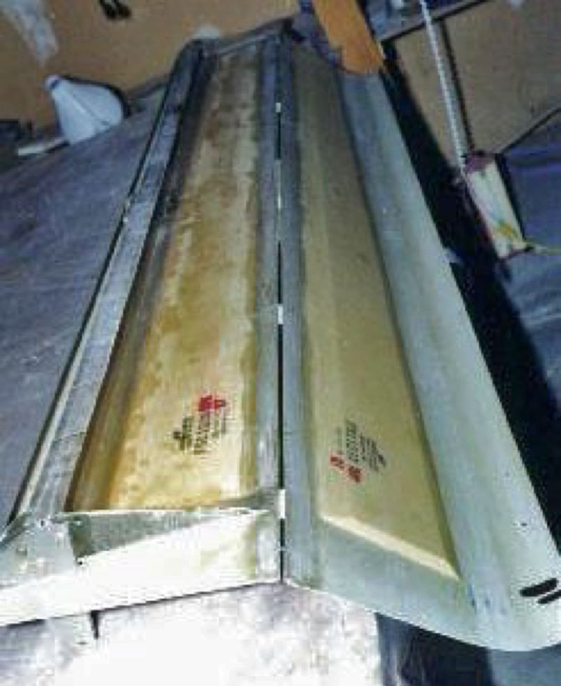
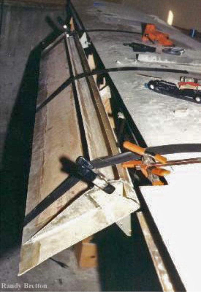
Build a detachable trailing edge board.
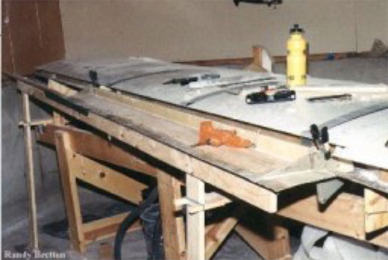
I used a 1×4 (or 2) long enough to build flaps, ailerons, and extended tips on. A 1x1x 1/16 aluminum angle (1/8 would have been better) was attached to this board with wood screws. Two 1×4 legs were attached to the board with single wood screws. The legs extend to the shop floor, and were supported horizontally by 1x4s protruding from the wing jig. This trailing edge jig is easily adjusted. Put shims under either leg to adjust the height and level it to your cord line. To adjust the cord, just slide the horizontal supports forward or aft. When you are satisfied with the alignment, glue 1×1 blocks of wood around the legs and horizontal supports. Secure the position of the legs on the floor using wood blocks and Bondo. Wrap the legs in plastic wrap so they don’t stick. Now everything is indexed in place and can be easily disassembled and reassembled. The aluminum angle will support the trailing edge of the flaps. To support the leading edge of the flaps hot glue tabs to the lower skin of the wing. Also, hot glue blocks of wood to the aft shearweb cap with the appropriate number of duct tape shims to locate the flap leading edge forward and aft.
Build as much of the flap as you can on the trailing edge board, or work on the bench and move the assembly to the trailing edge board to cure.
Completely assemble the hinges
Attach plates were trimmed where necessary, and attach angles were cut. Everything is riveted together. If I were to do this again I would make the attach angles on the outboard hinges a bit longer than called for in the forward dimension and the center flap hinges longer in the aft dimension. This will allow more margin when drilling the holes later.
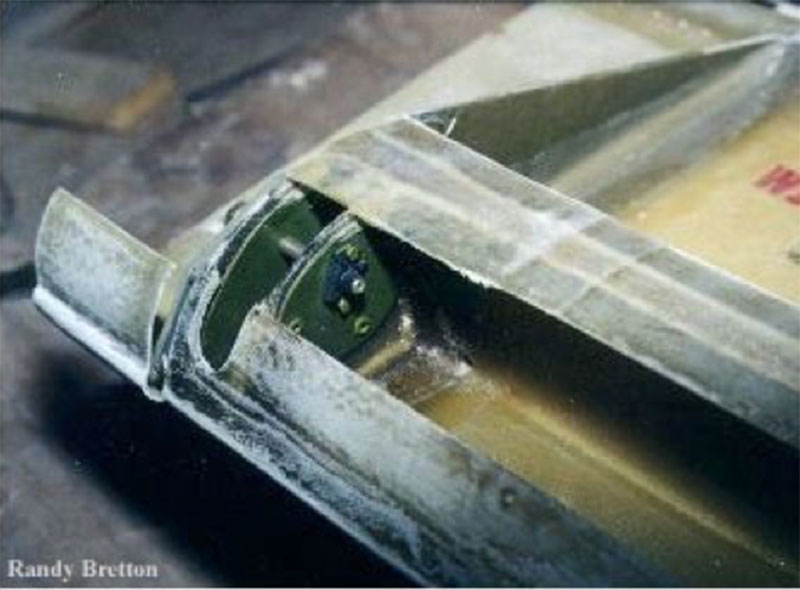
Mount the hinges on the wing
Mount the inboard and outboard wing hinge assemblies first. This was done by first bolting the hinges to a straight edge with small pieces of aluminum angle. The angles were held to the straight edge with super glue. Match the locations marked on the wing. Then slide the templates provided with the kit over the hinge bolt. The templates were glued to 1/4 plywood and modified so that the trailing edge may rest ON the extension board (cord line) instead of under it. Line up the template with the trailing edge of the wing as indicated. The forward part of the jig-hinge-template assembly may be supported by shims positioned on the aft shear web cap and beneath the over hanging portion of the attach plate. The trailing edge of the template rests on the aft extension board. Both inboard and out board hinges may be then indexed in place by hot gluing small wooden blocks around them. Check to see that the hinge jig assembly can be removed and slid back into the same position. Wax the hinge attach angles, and add a milled fiber resin mixture to pot the hinges in place. Check positioning with templates. When the resin has cured this temporary attachment will be strong enough for you to finish building the flaps. This allows you to check the movement and alignment of the hinges flaps at any stage of assembly before you drill the holes through the attach angles and wing. To mount the center hinge, loosen the nuts on the inboard and outboard hinges so the straight edge can pivot in place. Bolt the middle hinge to the straight edge such that the weight of the straight edge will revolve the hinge up against the bottom of the wing. Presto it’s aligned! Just wax it and pot it in place with a milled fiber resin mixture.
Build the flaps around the hinges.
The first step is to trim the flap skins. At this point, I will refer to Troy Scott’s method of determining the height of the flaps. This is on the Glasair News Web in the
Builders Hints and in a previous Glasair Newsletter. It works very well and is not difficult. After I installed the shear web and ribs, I use this method to adjust the height.
Continue building the flaps as instructed in the manual. When you bond the shear web cap to the sheer web, be sure to do that with the flap in position on the trailing edge board.
When it comes time to locate the center flap hinge, mount the flap on the extension board and use the wing hinge to position the flap hinge. Then use milled fiber to secure it as you did the others. I found it necessary to make the attach angles on the center flap hinge extend further aft to avoid mounting a nut plate under the shear web.
Close the flaps and position on the trailing edge board
This step was done solo. I made a duct tape hinge on the trailing edge and let the top skin hang off the work bench so I could add the milled fiber resin mixture to the leading edge area without it flowing off. Metal screws near the leading edge were used as shown in the manual. The flap was moved to the extension board to cure. Bolts were in place in the hinges and the trailing edge was secured with another straight edge, 4 clecos and about 50 clothes pins.
Drill holes in attach angles and wing
When the flaps had cured I removed the trailing edge board and checked the movement. When I was satisfied that there was no need of further adjustment I drilled pilot holes through the attach angles and spar cap. I used the measurements I made before wing closing to locate these holes forward and aft relative to the shear web cap.
Install nutplates through the inspection holes.
At his point I made a 4-foot round rotating wing jig and transferred the wing to that. With the wing positioned leading edge down and working through the inspection holes, I drilled out the pilot holes and drilled holes in the nutplates at the same time. If you put a piece of double-stick carpet tape on the plates, you can hold them in place without them sliding around. Try not to drill holes in your fingers. To bond the nutplates in place I cut and drilled a 3 laminate pre-cure the size of the nutplates and riveted it to the bottom of the nutplates. This large surface area will provide bonding area and eliminate the need for making more holes in the shear web cap. I installed the nutplates with wing inverted. To accomplish this I cut the heads off some screws, waxed them, and inserted them into the nutplates. I added a milled fiber and resin mixture to the pre-cured plates and placed them in the wing by pushing the screws up through the holes. I then threaded nuts onto the screws to hold them in place while they cured. Before you do this step you can check to see if the nutplate pads inside the wing are level. The screws should protrude equal lengths. If they do not you can adjust the pads with more milled fiber.
I made one more adjustment after this. The hinges were not all hitting the stops at the same time. I found that putting a 1 or 2 laminate shim under the trailing edge of the offending wing hinge solved the problem with out seriously changing the alignment.
If you have gotten this far you’ll have no trouble with the addition of nutplates and extra laminates aft of the shear web. I can add that it is nice to be able to roll the wing around and the rotating jig is worth the effort to build. It also makes it easier to install the flap push rod linkages with the wing inverted. After push rod linkage, I’ll installing the flap motor, and then the wing trailing edge extension.


