Stoddard-Hamilton instructs the builder to match and blend the lines of the cowl to the fuselage then shim the engine motor mounts to center the prop flange in the cowl opening. While this method is quick, it depends on accurate firewall placement and proper motor mount construction by Stoddard-Hamilton. Not being sure of either, I looked around for another method to insure accuracy.
First of all, we have to determine our requirements.
- On all Glasairs, the engine/propeller thrust centerline must pass through the intersection of BL0, the vertical centerline and WL100, the horizontal centerline.
- On Hartzell propellers using the HCC2YK-1BF hub, this intersection is 4.187 inches forward of the aft end of the propeller flange. Those with McCauley propellers will have to check with the McCauley factory for the thrust centerline distance, but I believe it is the same.
- On a Glasair III the thrust offset for the propeller at the thrust centerline intersection is 0 degrees down and 1.5 degrees right. On the Glasair II the offset is 1 degree up and 2 degrees right.
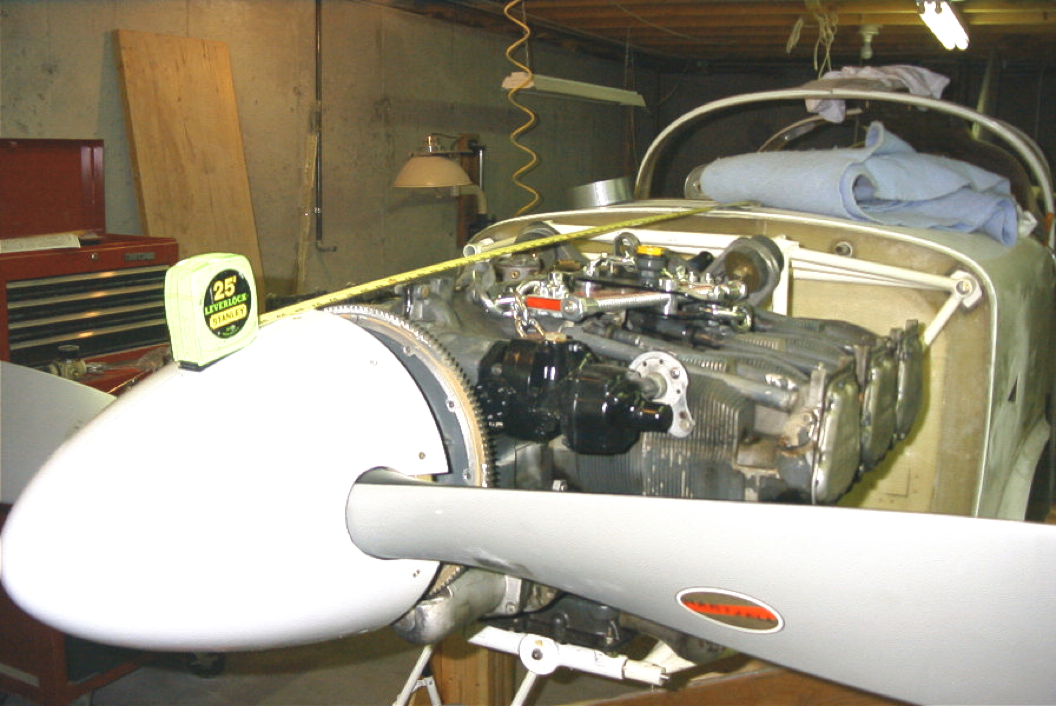
- On a Glasair III the forward edge of the cowl is 1.3 inches in front of the flat of the starter ring gear.
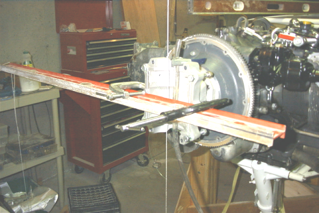
In order to complete this task, we’re using a scrap HCC2YK hub and Fred Van Raden’s cowling alignment disk. We’re also going to need a good engine lift equipped with a load leveler, some nylon string, a water level, a smart level, and lots of plumb bobs.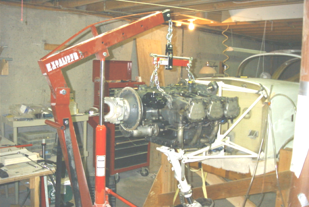
Step 1- Install the engine and level the airplane in roll and pitch. If your wing is not mounted to the fuselage, level the roll axis using the tips of the horizontal stab, otherwise use the wing tips.
 Step 2 – String an overhead line from the tip of the vertical stab. to a point forward of the engine prop hub. Tie the line off to a pipe or other fixture that will allow you to slide the forward tie point left or right.
 Step 3 – Drop a plumb bob from the overhead line between your forward wing mounts. Mount a wood spacer between your wing mounts on which you’ve marked the centerline of the airplane. Now move the forward tie point of the overhead line left or right until the plumb bob hits your marked centerline at the wing. Mark the tie off point at the forward overhead line so we don’t loose the reference. What we’ve done here is to extend BL0 forward of the engine.
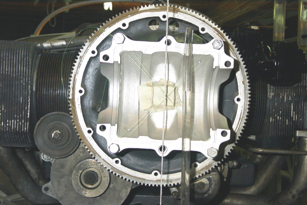
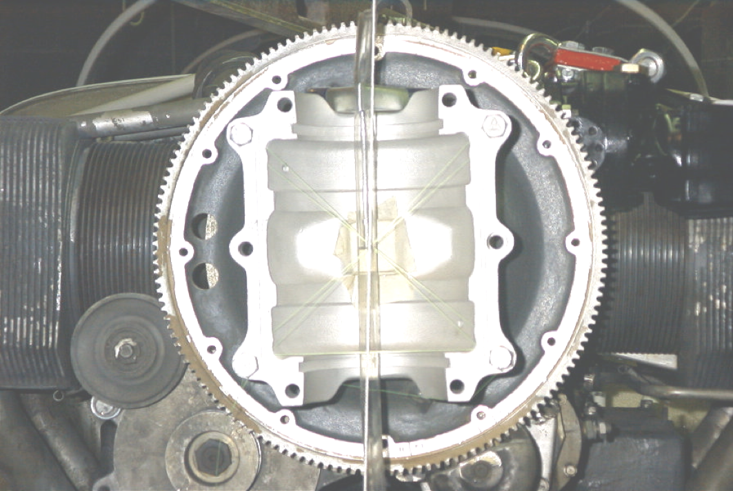
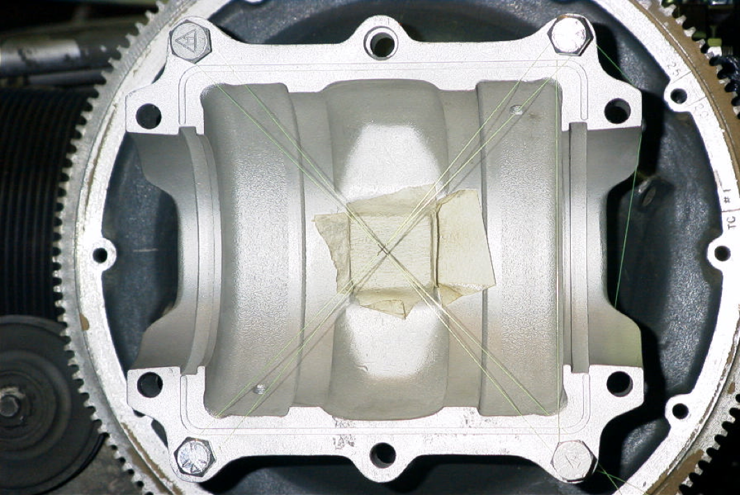 Step 4 – Mount the ring gear and the scrap HCC2YK-1BF hub. By splitting the hub and stringing fishing line in a figure 8 between the bolts, the thrust centerline of the prop is determined and marked.
 Step 5 – Now, all we have to do is drop a plumb line from the overhead line in front of the hub and, using a water level, transfer WL100 to the face of the hub. As you can see from the pictures, mine has to move about 1/16 right and 1/4 inch up.
 Step 6 – Shimming, I don’t like to shim at the motor mount. It makes removal/installation of the engine very difficult. I shimmed at the firewall with 0.125 at the bottom and .032 at the left attach points. As you can see, the results after shimming were good. I’ll replace the aluminum shims with laminates prior to cowling installation.
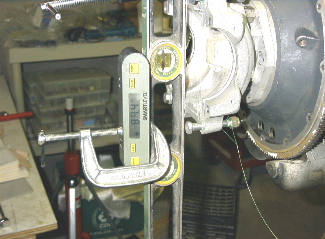 Step 7 – By using a smart level across the flats of the prop hub split we can measure the down thrust directly. Mine was 0.6 degrees up thrust. Measuring left/right thrust offset is going to be more difficult.
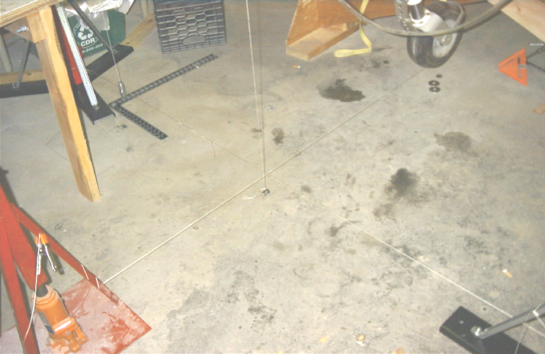 Transfer BL0 to the floor using the plumb bob at the wing centerline and the plumb bob in front of the engine. Draw or string a line on the floor 90 degrees to the BL0 line at the front of the engine even with a line dropped from the prop hub split line. The easiest way to ensure a true 90 degree angle is to use the 3, 4, 5 method of right triangle geometry.
 Once you’ve got your floor lines, mark a 4 foot level with a 3 foot mark. Hold the 4 foot level across the flats of the prop hub with the 3 foot mark on the BL0 centerline at the hub. Drop a plumb line from the aft tip of the level to the floor and measure the distance to your 90 degree line. As you can see, mine was 0.75 inches.
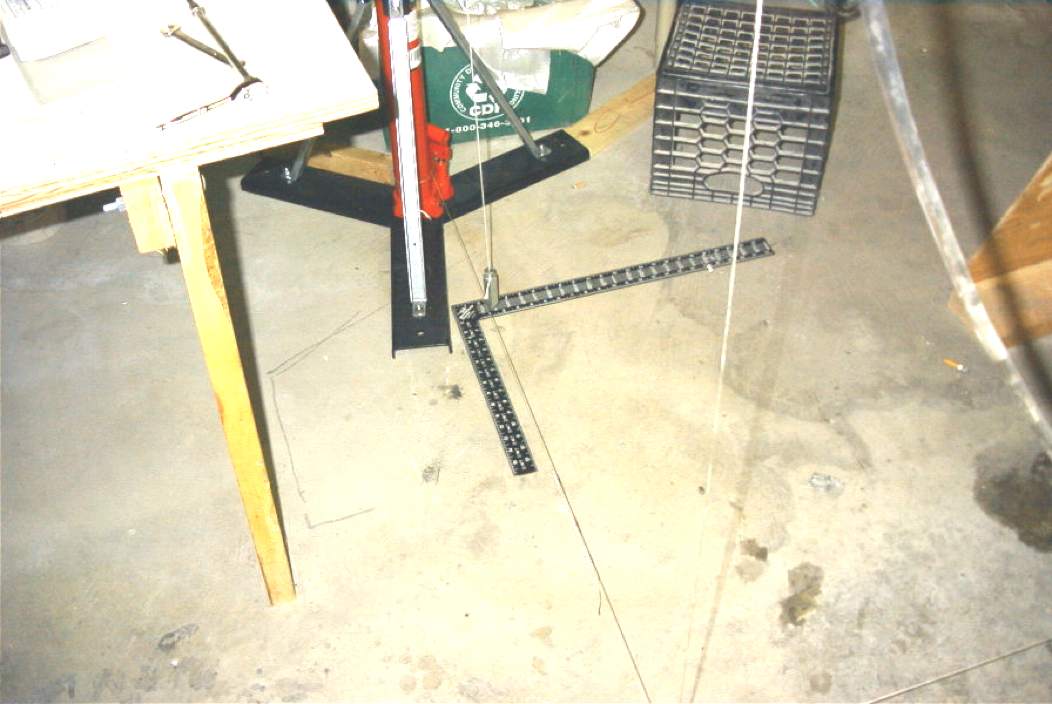 Those engineering types can pull out their scientific calculators, but for most of us, it’s easier to go to http://www.1728.com/pythgorn.htm and type in your values. Mine (0.75 and 36) gave me a right thrust offset of 1.2 degrees.
It’s possible to over shim at the firewall and counter shim at the motor mount to bring the engine alignment and offsets to the desired 0/1.5 condition. But is it worth all the time and work? I don’t think so. As long as you’re within a couple of degrees of optimum, the airplane will fly fine. If you were 3 or more degrees out in any direction, I’d give some thought to correcting it.
You’ll notice that I used string lines on the floor. One benefit of this is that it allows us to mark BL0 at several needed points on the fuselage. Mark the fuselage cowling flange, the top centerline at the vertical stab fairing and, by transferring up from your lower line, the bottom centerline of the aft fuselage. Because I’m also installing a ventral fin and extended rudder kit, the bottom centerline is important to me. Now take a small triangular file and make a small notch (1/8″) in the leading edge of the fuselage cowling flange at left and right WL100 and top and bottom BL0. Do the same at the tail. These notches will serve as permanent markers for WL100 and BL0.
At this point, the engine is perfectly aligned and the thrust offsets have been found to be within acceptable limits or corrected.
Spinner Installation
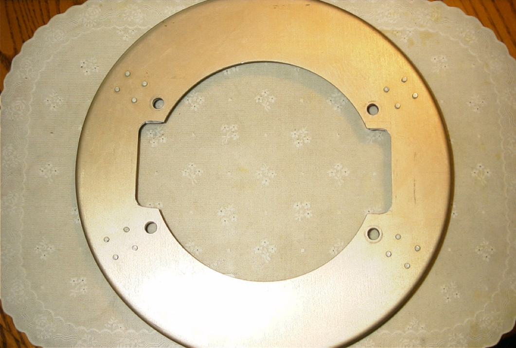
Spinner installation is straight forward as described in the SH manual unless you’re fitting a Hartzell propeller manufactured after 1998. If this is the case, as it was for me, I have enclosed page 9 of the spinner service letter from Hartzell that gives the dimensions for the needed changes to the SH back plate. In essence, Hartzell changed the blade retaining method for HCC2YK hubs in 1999, which necessitated a change to the hub casting. As a result, the SH back plate for the Hartzell propeller needs some major modifications to fit the propeller.
 Before you remove the spinner for the last time, make sure you take an accurate measurement of the distance from the aft of the spinner to the aft of the fuselage cowling flange. This measurement will vary somewhat per installation. Mine was 43 and 9/16 inches.