Submitted by Charles Lutin
 While building my Glasair Super II, I have been highly impressed at the strength and quality of the construction produced by these methods even by a novice such as myself. While building up the ailerons, however, I was unhappy with the counterweight installation in that the counterweights seemed to want a little more support on the outboard side. There was a little bit of wiggle and twist left in the installation even after bolts were installed, due I believe to compression of the 1/4″ foam in the outboard aileron rib. After looking at this a few days and being unhappy I have devised, I think, an improvement to the design, which I will call an aileron counterweight support rib.
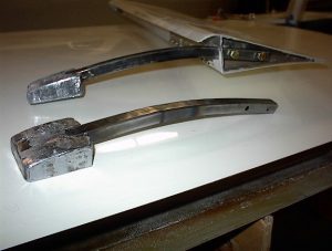
Outboard end of left aileron, viewed from forward side. The construction sequence is as follows, after closing the aileron and re-drilling holes through aileron outboard rib.
- Take a piece of 2-layer pre-cured laminate, cut to size for fit up inside outboard end of aileron.
- Locate and drill 3/16″ holes in the locations bolts will pass through into the aileron counterweight arm. Enlarge 1/64″ more after drilling.
- Affix one or more DIO washers on the inboard side of this rib to produce the desired 1/4″ distance from the end of the aileron, when a bolt is passed through the rib, washers, counterweight arm and nutplate. Build up a small mill fiber fillet around this washer(s) and cover with a one layer laminate. Trim in the green cure state, including cloth over the washers so that metal to metal contact will be ensured. Recheck fit.
- Wax counterweight arm and bolts, then put mill fiber mixture along outboard rib and temporarily install counterweight arm, making flat surface for counterweight arm to rest on and building up slight humps to each side with squeezed out resin/mill fiber. Let cure. Take care to not get mill fiber mix into nutplates.
- Remove counterweight arm, wax bolts and arm, temporarily install again with counterweight support rib. Bolt lightly in place, then put a few dabs of mill fiber mixture around perimeter to hold rib in place. Cure.
- Remove counterweight and bolts, build up a small mill fiber radius around perimeter of counterweight support rib and cover while mill fiber mixture is wet with two layers of cloth. Trim. Let cure, then re-drill holes through washers.
Estimated construction time 2 hours each side, though I fiddled with this a good bit until correct. The evident strength of this important installation is greatly improved, as evidenced by the wiggle and twist test. Weight is minimal (20 gr. each side?).
In addition to the improvement in strength, this installation will allow inspection of the bolt heads on preflight walk around and the use of drilled head bolts and safetying. I may be gilding the lily here but I know I don’t want one of those counterweights vibrating the bolts out on a dark night in the clouds. My ailerons want AN3-H3A hardware; this will probably be variable.


