There are two check valves installed within the upper housing of the FVFV. One valve is designed to open to allow pressure into the tank in the event of a vacuum within the tank and the second valve is designed to open in the event of the tank pressurizing. These valves have a rubber seal and are spring-loaded against their seat. If either valve is not seated, fuel can leak past the valve when the wing tank is full. We have seen instances where the FVFV sat unused for some time and the seals had become dry and the internal valves prone to sticking.
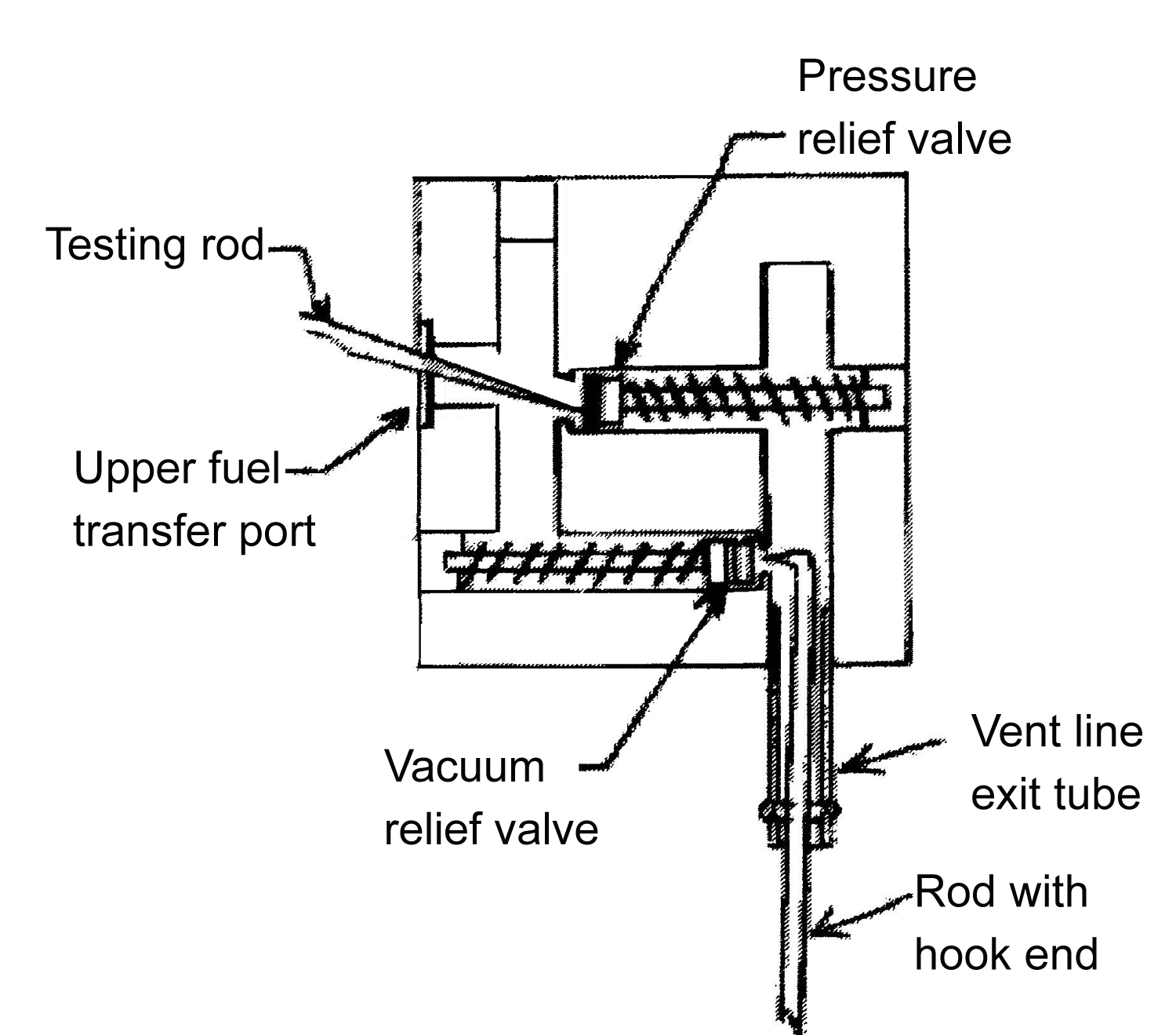
The valves can be checked for function very simply. First the FVFV body must be removed from the wing by removing the four long horizontal screws holding the FVFV to mounting plate and disconnecting the vent line exiting the FVFV. Figure 1 shows a representation of the internal configuration of the FVFV top section.

The pressure relief valve is visible through the upper fuel transfer port in the top of the FVFV. Its function can be tested using a small rod or scribe. The valve should move smoothly and freely through a travel range of approximately 1/8″. The vacuum relief valve cannot be viewed directly, but can be accessed through the vent line exit tube of the FVFV. The vacuum relief valve can be tested using a short hook on the end of a rod inserted through pressed in the vent line tube. This valve should also move smoothly and freely through a travel range of 1/8″. If the valves do not move freely use a spray lubricant such as WD-40 to lubricate the seal and free up the valve. Use the testing rod to move the valve in and out until free movement exists. The FVFV can then be function-tested by plugging all ports on the FVFV that may be open except for the upper fuel transfer port. When the pressure and vacuum valves are seated correctly, no air passage will be allowed out the vent tube. When blowing in the fuel transfer port, the float within the valve will first move upward and seal after which no air movement should occur.
If the valves cannot be made to move freely or to seat the upper body of the FVFV, it should be returned to Glasair Aviation for repair or replacement. Prior to returning the valve a Return Authorization number should be procured from the company Quality Control department and warranty coverage determined.


I’m after information regarding the type of hydraulic pressure switch supplied in the Glasair 11 kits ?
Pressure setting, normally open or closed? Etc