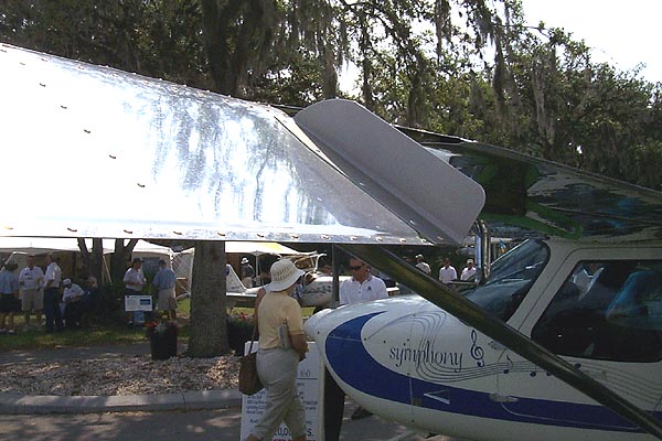
Just to show there are multiple ways to skin a cat, we are showing how some things are done on the OMF Symphony. -Editor
We spent a lot of time with the Symphony folks and did a lot of measuring of the vortex generators, their placement and the fences on both ends of each aileron.
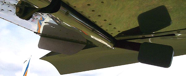
Aileron Fences
The fences are angles (bent) sheet Aluminum. They are 9-1/2″ long and the forward side is curved. The curve goes (straight) after running 2-1/2″ rearward. The inboard leg of the fence angle, (the part that attaches to the aileron) is also 9-1/2″ long and is 1-3/4″ wide. The forward end narrows (slants) down to about 1-1/4″. The narrowing starts about 2-1/2″ from the forward end.
As far as I could see, the attachment to the aileron seemed to be mostly at the inboard side of these angles, towards the center of the aileron, (the outer edge of the angle ) . The angle curve nested (over) the outer most aileron rib rivets. (No attachment to this rib or its rivets). I could not tell if there was any interior reinforcement inside the aileron to stiffen up the area of the rivet attach) I noted that some cherry rivets were used but did note if they were all cherries. If they just cherry-riveted through the thin skin, I am sure that the vibration of the air flow, would eventually crack the skin around the rivets. One thing for sure, you do not want these fences to crack loose and jam the ailerons.
It was mentioned duct taping them on for a test. I think I would add 2 or 3 cherries besides the tape. What we used to call 500 mile per hour aluminum tape, would be a better bet than duct tape.
 The Symphony was FAA certified the day before Sun ‘n Fun opened so had to be certified with the generators and fences in place. If they worked for flight certification envelopes, during both the German certification and the US FAA certification, they should need no further testing by GlaStar owners, as the wing and aileron is supposed to be exactly the same airfoil as we have.
If I were making an attachment of the fences, I would probably lay a thin reinforcement sheet of metal on the attach leg, lay out a rivet pattern, secure the angle into place on the aileron and secure the backup sheet on top of the fence leg. Drill through through the sheet and through the fence and wing skin. Deburr. Open up the trailing edge of the aileron as needed. Drop two pieces of thin safety wire down the fore and aft most holes and out the trailing edge. secure these wires into the fore and aft holes of the reinforcement plate. Stuff everything inside the aileron and pull into position with the wires. Cleco into place and cherry rivet.
NOTE: The outer fence on (each) aileron, hangs down. The inboard fence on each aileron points up – four fences in all.
Vortex Generators
The Symphony has two forward of the Aileron and none at the wing root end as called out in our manual. I took measurements of them and will compare size and angles when I get ahold of ours to make a comparison.
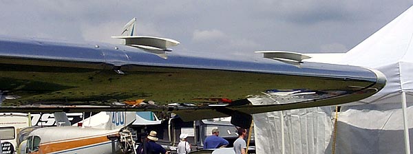
The outer most vortex generator is located 18″ from the outboard end of the wing proper (not the plastic tip but the screw line that holds the tip on).
The next one is located 24″ further inboard from the first one. The nose of the generators are mounted vertically in line with the forward edge of the wings leading edge.
I have an idea the generators and the fences work together. I doubt that the fences alone would do much as much. The German engineer said that this set up lowered low speed control by several knots. He did not nail it down.
I do not know just when we will try this out since our ailerons are already balanced, but we will eventually do it. More low speed control equates to more safety and we need all of that we can get.
The Symphony did not have the inboard vortex generator next to the fuselage but I think we will use one there. They (Arlington Aircraft), did not just put it there for the hell of it. I am told by engineering types that Vortex generators produce little drag.


Has anyone flown an airplane without the fences and then with the fences installed? A flight report would be great if anyone has done it.