During the process of final-rigging of the ailerons in our early-model Sportsman it became abundantly clear that a very small number of improvements to the kit would make aileron rigging a breeze.
What are these improvements, you might ask?
- Holes drilled in the aileron bell cranks and adjacent structure to allow the insertion of rigging pins to rigidly hold the bellcranks perpendicular to the spar.
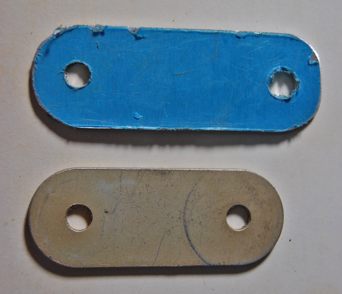
- A template or drawing to fabricate, from a sheet of locally-sourced plywood, a rigging tool to hold the control sticks in perfectly vertical orientation.
- A set of instructions which clearly explain how little adjustment on the turnbuckles is required to achieve very large changes in cable tension, along with clearly-worded text to suggest that achieving proper cable tension may not always be possible if using the turnbuckle locking clips and that one may have to resort to safety wiring the turnbuckles in order to achieve proper control deflections while also achieving proper cable tension.
When we spent the time to set up the basic rigging conditions as perfectly as possible, it was relatively easy to achieve perfect control surface travels. If I could re-write the builder’s manual I would summarize the process in this manner:
- Slacken all three aileron turnbuckles as much as possible while keeping some small amount of thread in each end engaged in the turnbuckle barrel—verify that the barrel engages equally the left and right threaded cable ends. If not equal, adjust so the same number of threads are engaged in both the left and right end of the turnbuckle barrel.
- Clamp flaps in the fully retracted position using clamps on the flap tracks.
- Clamp ailerons to flaps such that the lower skin of the aileron is level with the lower skin of the flap in order to achieve the aileron neutral position.
- Adjust aileron pushrod length such that the aileron bellcrank is perfectly perpendicular to the spar when the aileron is clamped in the neutral position.
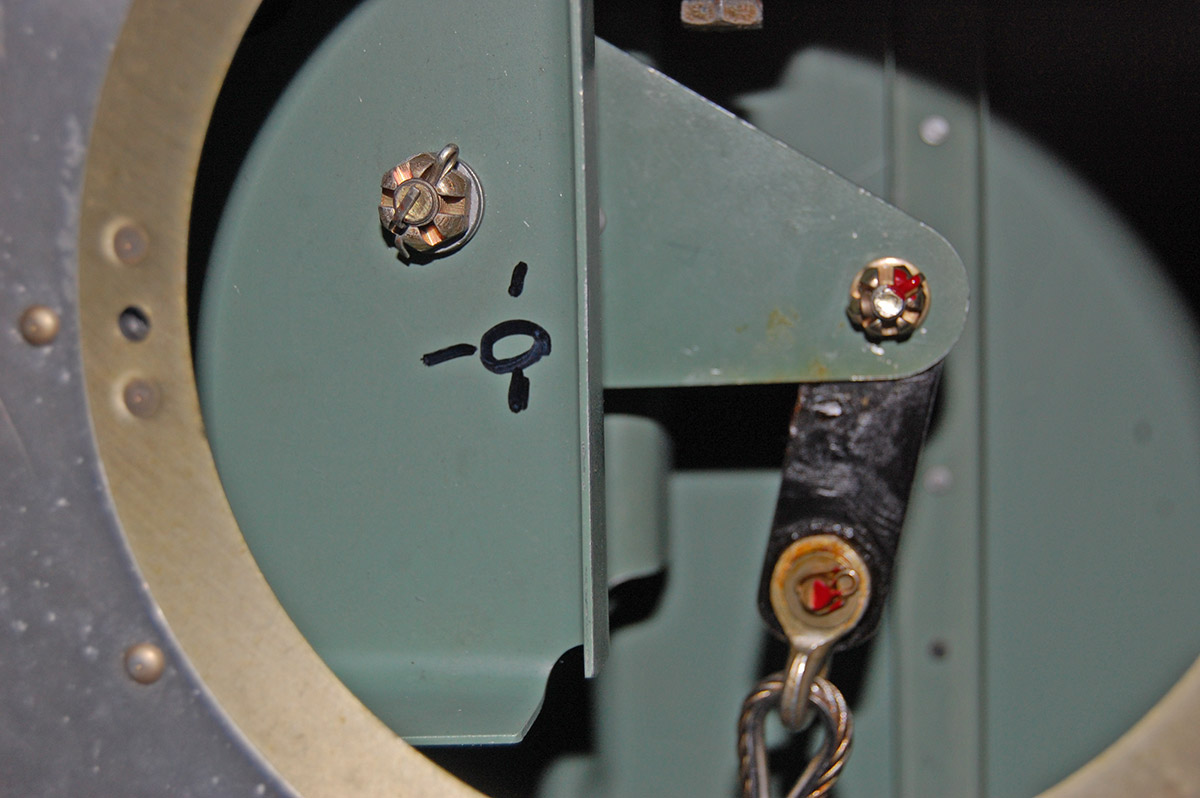
- Use a digital level to rig the 17.5-degree downward travel stop at the aileron bellcrank.
- Use a digital level to move one control stick to the perfectly vertical position; measure the second stick’s angle relative to the “wings level” attitude of the aircraft. If both sticks are not perfectly vertical, adjust the length of the cross-connect rod until both sticks are perfectly level. Make adjustments in equal measure to the left and right side forks on the cross-connect rod.
- Use a rigging tool (plywood with a notch cut to hold one control stick in a vertical position while the ends of the plywood are wedged between an outboard cage tube and the cage tube of the center tunnel).
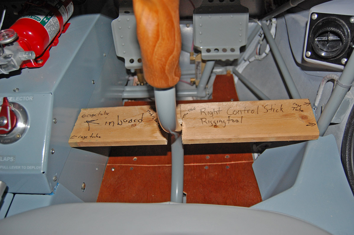
Rigging jig used to hold the right control stick in a vertical orientation. - With all of the above conditions met, and with control sticks rigged in the vertical position and ailerons clamped in the neutral position, slowly tighten the three turnbuckles equally—be careful as a small turn on each turnbuckle equates to a large increase in cable tension.
- Once the aileron cables are with in the specified tension range, unclamp the ailerons and control sticks and move the controls through the full range of travel several times.
- Verify proper aileron deflection (up 22.5 degrees, down 17.5 degrees) and proper cable tension before applying the appropriate technique to safety the turnbuckles.
We found that following this technique made the entire process quite easy and yielded perfect results. We also found that a tool to hold the cable ends from turning while adjusting the turnbuckles was an indispensable aid in the process. We manufactured three such tools from metal coat hangers.
Once again, I do hope somebody from the factory will read this and consider adding to the design proper rigging tools to make this process faster and easier. Having to rig using clamps, masking tape and small machinists squares is more than a little Mickey-mouse for an airplane kit that costs as much as three cars.


fantastic ‘how-to’ for us neophytes….thanks Mark for an impeccably drafted treatise on cable management!
This should be a ‘document’ in the library, so I can find it for next year’s annual!
I think those ‘locally sourced’ plywood templates give me an idea for a new gustlock!…..thanks for the bonus!
…now, aren’t you supposed to be getting some transition training about now??? 😉
Thanks for the kind words, Perry.
Aileron rigging took two of us four days to get right. It took about three days before we convinced ourselves there was no way we could possibly get them rigged properly using the CAC-built crossover cable interconnects. Once we decided the factory had done it wrong we had license to actually do it right. The end result is a pair of ailerons that are rigged almost exactly to the nomical factory specified deflection angles. Very satisfying.
As for transition training, well, I think I need to have a word with the weather man in hopes of getting some even mildly-cooperative weather since the last six weeks have been pretty rotten around here.