Conversion from manual to electric electrically operated flaps on GlaStar N99RN
IMPORTANT NOTE: The following article has been prepared for informational use only as it describes the operation of an experimental electric flap conversion system developed for use on GlaStar N99RN. This aircraft experimenter does not endorse the use of this system in aircraft other than N99RN. Therefore, installation/ use of this system is solely at the risk of the owner/operator and the designer assumes no liability.
Operational description
The system involves the removal of the mechanical flap handle and ratchet plate. The electrically operated linear actuator system will be connected to the flap cable attach tab [part no.14] that is presently used to connect the flap cables and the weldment located forward of the co-pilot seat. Therefore, although it is necessary to remove the flap handle completely, it is not necessary to disconnect the cables from the flap cable attach tab fitting.
It will be necessary to construct a new flap actuation lever to replace the lower end of the mechanical flap mechanism. Before removing the mechanical flap handle/ratchet parts note the measurement of the zero, 20-degree, and 40-degree flap hole location in the center of the flap cable attach tab. A reference of the 1/2″ vertical tubing located near the flap tab should indicate approximately 1-1/2″ for the zero deflection, 3″ for 20 degrees, and 4-1/2″ for 40 degrees. These measurements will be used to adjust the linear actuator for the correct travel.
The new flap actuation lever will have a 3/16″hole located for the 3″ travel necessary for the full movement of the flaps and another 1/4″ hole located below it nor the attachment of the linear actuator. It will be necessary to bend an offset in the flap actuation lever to clear the flap cables as the move for and aft. Therefore, make the necessary bends before calculating the exact location of the holes for the flap attaches tab and the linear actuator. Also, it will be necessary to attach the magnetic portion of the proximity switch to the side of the new flap actuation lever. The magnet will face the center of the aircraft.
The proximity switch will be attached to an aluminum plate which needs to be clamped to the 1/2′ tubing next to the flap attach tab. The plate location is not critical. However, it will be necessary to plan for the attachment of the proximity switch in such a manner as to facilitate the eventual adjustment of the switch for the 20 degree flap stop. The linear actuator has built-in switches so there is no need for any other type of switching device for the full up and 40 degree positions.
Two fittings must be fabricated to attach the linear actuator to the aircraft. Pieces of steel tubing are cut and welded to the rod ends listed in the bill of materials. A clevis and ball type rod end is installed for
later attachment to the airframe.
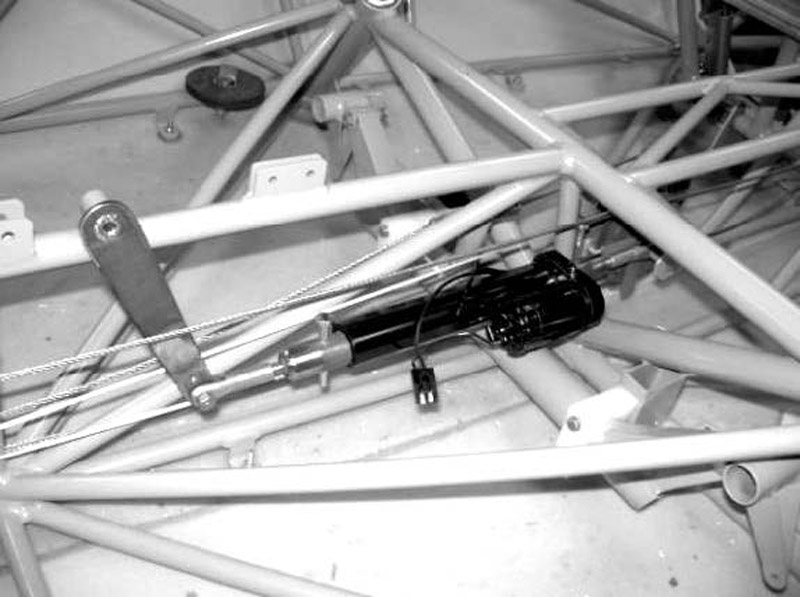
A Warner 12V linear actuator is installed under the co-pilot seat. Attachment is made between the existing flap cable attach tab fitting [previously attached to the lower end of the flap handle] and welded tab used to bolt the cable reversing pulley. The tab is located just forward of the front edge of the co-pilot’s seat. It will be necessary to remove the tension on the flap cables in order to remove the bolt and attach the linear actuator with the clevis straddling the weldment tab. The bolt original bolt is part no. 128, AN4-43 drilled shank bolt.
It will be necessary to drill the 1/4″ hole in the steel pulley weldment to 5/16″. A steel bushing will be inserted through the clevis and the weldment and the 1/4″ bolt reinstalled to hold the entire assembly together. After the actuator with the rod end and the clevis has been installed, the tension previously released on the flap cables can be reapplied.
The electrical switches, relay, and circuit breaker are now installed with required wiring to the proximity switch. With the system completely installed begin actuation of the flaps to determine whether any adjustments are necessary. If careful measurements were initially recorded before the conversion and the holes located properly in the flap actuation lever, it should not be necessary to make any other adjustments.
One last note: It may be necessary make a cut-out along the inside corner of the seat pan to provide clearance for the liner actuator since there is some vertical movement as it moves the flap attach tab. Also, it is a good idea to install a hatch so that periodic checks can be made on the system. The hatch could be made of aluminum and be located along the forward slope of the co-pilot seat pan.
Electric flap parts list
- Linear actuator- Warner Electric, part no. WAR S12-17A8-04
- 1 clevis terminal – AN 665-46R
- 1-rod end – F45-19
- 1 threaded rod end- AN 490HT 10 P
- 1 threaded rod end- AN 490HT 11 P
- 1 pc. Steel tubing 1 3/8″X 3/4″OD – .058 wall thickness
- 1 pc. Steel tubing 13/8″ X7/8″OD -.058 wall thickness
- 1 pc. Steel bushing stock approximately 1″ long – 5/16″OD, ¼”ID
- 2 AN 315-5 jamb nuts
- 1 AN 4-12A bolt
- 1 AN 4-10A bolt
- 1 AN 4-10 bolt
- 6 AN 960-4 washers
- 1 AN 310-4 castle nut
- 3 AN 364-4 locking nuts
- 1 1/16″ X1″ cotter pin
- 1 pc. .040 2024 aluminum 6″X6″
- 3 1/2″ tubing clamps
- 1 proximity switch Hamlin part no. 59135-010-nd
- 1 proximity magnet Hamlin part no. 57135-000-nd
- 1 relay Omron part no. z981-nd
- 1 dpdt toggle switch 10 amp [20 degree switch]
- 1 spst toggle switch 10 amp [40 degree switch]
- 1 circuit breaker 7 amp
- 1 flap actuating arm 1/8’x1″ steel approximately 6″ long with a
- 3/8″X7/8″ bushing welded to the upper portion of the the arm.


