There have been numerous threads on the Glasair Owners Forum related to engine cooling and dealing with high oil temperatures and high cylinder head temperatures. It seems that as a general rule, the angle-valve engines are better at keeping CHTs in check, but struggle with high oil temperatures (due to their oil squirters at the back of the pistons) while parallel-valve engines seem to experience the exact opposite (since they don’t have the oil squirters). Having an angle valve engine (IO-390) I never had high CHTs until I changed from the factory setup to an electronic fuel injection and ignition setup which temporarily caused high CHTs due to a couple of mistakes made by the conversion kit maker. Once those were resolved, I was back to just having to deal with high oil temperatures, but still only on hot (over 80°) days.
Eventually, I set about to fix the problem once and for all by trying numerous ideas (many of which were found on the Glasair Owners website). More importantly, I measured the results obtained from each modification, so I can provide some data for others who are dealing with high temperatures.
Oil cooler
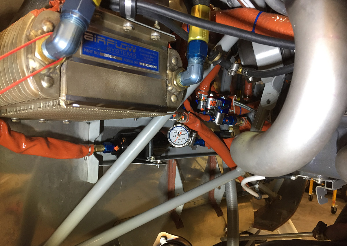
Since my problem started with high oil temperatures, the first thing I did was change the oil cooler. My plane was built as a TWTT amphibian at the Arlington factory in the summer of 2011. By the end of the summer of 2013 I had enough hours on the engine that break-in issues were clearly a thing of the past, so I changed from the TWTT oil cooler to an Airflow Systems oil cooler. A hot day was chosen, a test flight was conducted before changing coolers, then Glasair co-founder, Ted Setzer, helped me swap the coolers as quickly as possible to get back into the air in the same ambient conditions to redo the test flight and record the results. The new oil cooler reduced oil temps by an average of 7° Fahrenheit. Not a lot, but it helped some. Since I only experience the problem in particularly hot weather, and we don’t get much hot weather in Seattle, the oil temperature was generally only a problem when I crossed the Cascade Range in Washington or British Columbia where summer temperatures are commonly in the nineties or higher. Although that happened several times annually, the new oil cooler did a pretty good job, so I wasn’t in any hurry to go further.
Ted wasn’t sufficiently impressed with the 7° improvement I got from changing oil coolers, so he found a different one from the Aero Classics High Efficiency line. It doesn’t have as many rows as mine (14 vs 17), but he thought the design of the cooler may be more efficient and has had good luck with it (although he doesn’t have oil squirters so oil temp is less of an issue for him). One day, he suggested that I try his oil cooler, so once again, I did a test flight, swapped out coolers and test flew again on the same day. We saw no difference whatsoever. So, 14 (superior?) rows or 17 (inferior?) rows didn’t make any difference, because we just weren’t getting sufficient airflow over either cooler.
New electronic ignition and fuel injection
Then all hell broke loose. Ted helped me install the new electronic ignition and fuel injection system and on the first flight I saw my CHTs jump to 475°F within 2 minutes after takeoff! Ted said that he’d never seen high CHT’s on an IO-390 that didn’t have its ignition timing set too far advanced. Long story short, the electronic timing was waaaaay too far advanced, set at 34° BTDC instead of the factory 20°. People who know about such things as appropriate timing curves on angle valve engines gasp when you say 34° BTDC. Anyway, a quick reprogramming of the computers fixed that problem (mostly) but the CHTs were still higher than I recalled seeing previously. Ted thought the baffle seals looked a bit worn, so we replaced them, but it didn’t help. We also plugged every little nook and cranny and stiffened the front air dam to prevent blow by, but again no help. Then we looked at the spark plugs and found that the conversion kit came with the wrong plugs and plug adapters (short reach vs long reach) so it turned out that our ignition spark was started almost a half inch up inside the spark plug hole instead of down in the combustion chamber where it belongs. I called a different vendor and bought the proper reach adapters and plugs. The difference was amazing, as number three CHT dropped 60° just by changing that one thing! Now my CHTs are cooler than ever (typically cruising in the low 300’s vs. the mid 300’s before electronic fuel injection/ignition and the work we did on the baffling), but my oil temperature was still high on hot days, so I went to work fixing them.
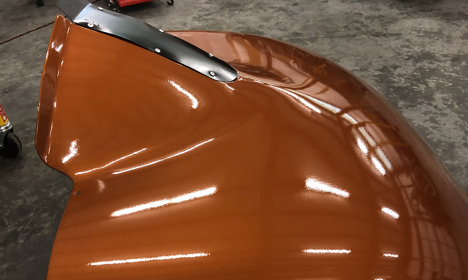
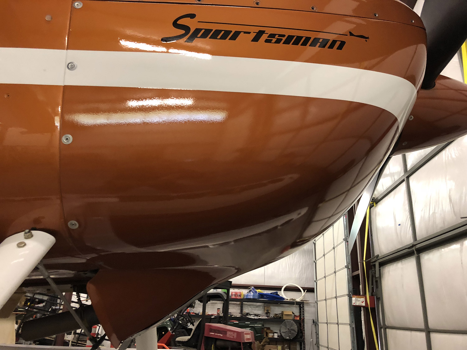
Focus on the cowling
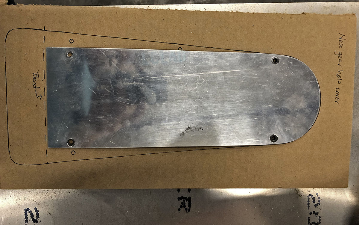
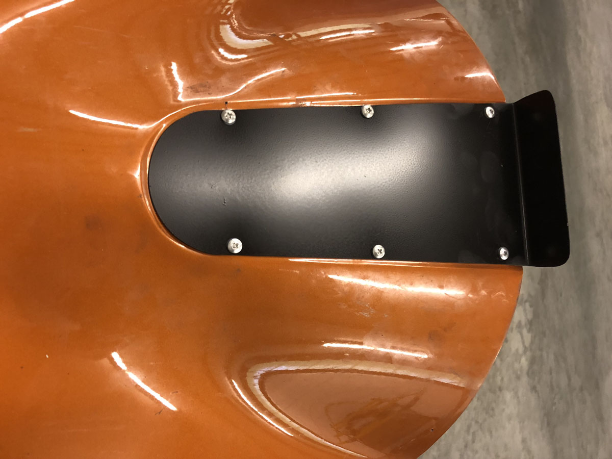
First, although the airplane lives most of the time on amphibian floats, it was built to be a nose dragger or a tail dragger as well. As a result, there is a cutout in the lower cowl for the nose gear and I decided to make a plate to cover it. Before doing so, however, I installed a manometer in order to get differential pressure readings so I could check for quantifiable improvements. Initially, I installed the manometer probes directly above and below the oil cooler, in order to see how much air flow I was getting over the cooler. I drilled holes in the plenum on top of the cooler in order to insert the top probe in the path of the cooling air and then safety wired the second probe to the bottom of the cooler. I flew in that manometer installation configuration and took various readings of pressure differential at various indicated airspeeds for both climb and cruise. Next, I removed the probes from the cooler, plugged the holes drilled in the oil cooler plenum and installed the probes above and below the engine to see if the readings were any different (I was curious as to whether the airflow over the oil cooler was restricted in some way, not getting as much cooling flow as the cylinder heads). It turns out that the readings were the same, so there was no restriction on the cooling air going over the oil cooler. My oil cooler is fed from a 4” SCAT tube installed in the baffling behind the number 3 cylinder. Next, I installed my cover plate and took the readings again and it turned out that the cover plate actually improved air flow by one-tenth of one inch of water column in both climb and cruise. Once again, not much improvement, but it helped a bit.
The manufacturer of my oil cooler told me we needed a minimum of 3” water column in order for the cooler to work. Climbing at 80 KIAS, my pressure differential was now at 2.2” of WC instead of its previous 2.1”. Using Bernoulli’s equation and assuming standard atmospherics at sea level, 2.2” WC translates into approximately an increase in cooling air speed through the cowl from 54.3 knots to 55.6 knots. Compared to the 80 knots indicated (and ignoring minor instrument error) the cooling system was only allowing air through at about only 70% efficiency. Clearly we had issues that could and should be rectified.
Many years ago, Mississippi State and Texas A&M collaborated on a study commissioned by NASA associated with air cooling of aircraft engines that resulted in a number of aircraft manufacturers changing their inlet shape to the now prevalent large round inlets seen on planes such as the Lancair Columbia/Cessna 350/400, Mooney Acclaim, Carbon Cub, Lancairs, etc. This design proved to be far more efficient at getting the cooling air into the cowl than anything that had been tried previously by aircraft designers. Glasair experimented with a similar concept by installing “cooling ramps” (available as an option) on the upper cowling of the GlaStar and Sportsman to help improve the inlet airflow. Ted helped me install those on my upper cowl and we saw absolutely no change in manometer reading, either in climb or in cruise. This proved that although the ramps may be helpful if the problem with the exit area was resolved, we nevertheless had a significant problem with that exit area.
The next thing we tried was an idea Ted had published a while back associated with replacing the two cowling screws on either side of the cooling air exit hole with longer ones and inserting small spacers (say half inch to one inch) between the cowl and its mounting flange. The result of a half inch spacer was an additional two-tenths of an inch of water column, getting us up to 2.4” at 80 KIAS, still nowhere near enough. One inch spacers added a bit more. Dennis Vanatta, a frequent poster on the Glasair forum and a Sportsman builder wrote about his success in improving cooling airflow by adding a lip to his exit hole angled down about 30 degrees, thereby disrupting the airflow from the lower cowl flowing over the exit hole apparently damming up the exit. I took Dennis up on his offer of allowing me to use his aluminum lip mold and I clecoed it to my bird and determined that it was worth another three-tenths of an inch of water column. Ted had previously done something similar to his cowl, but it wasn’t as elegant since he didn’t have access to a metal stretcher.
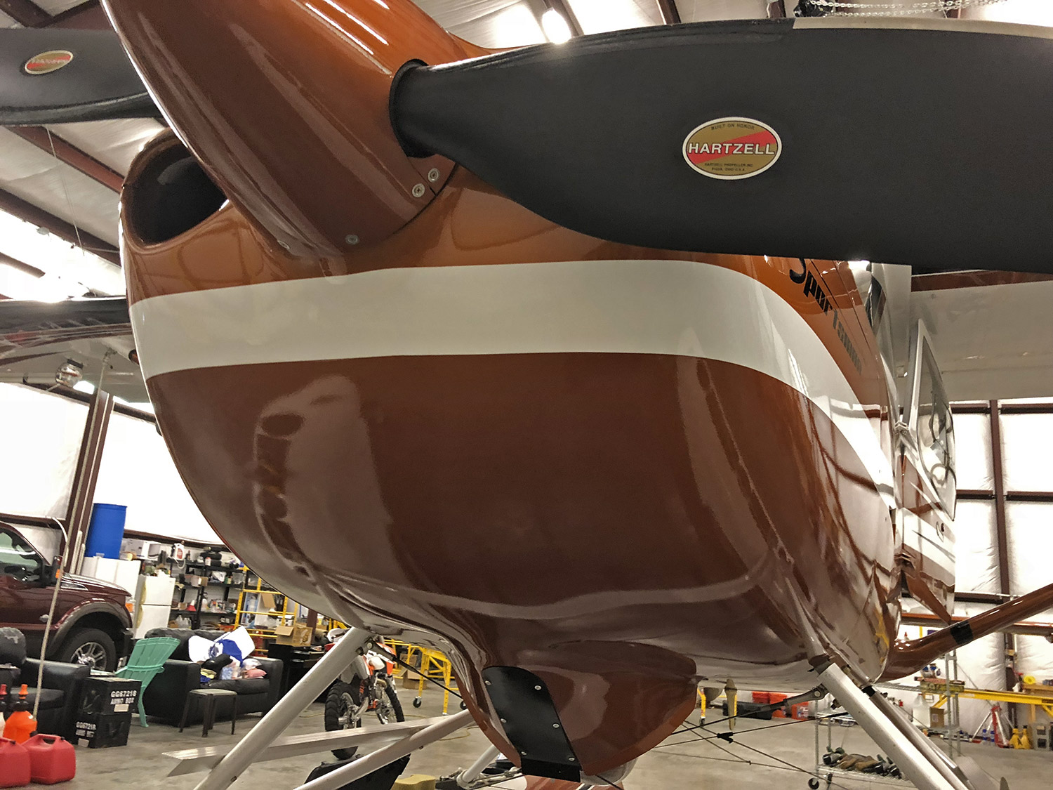
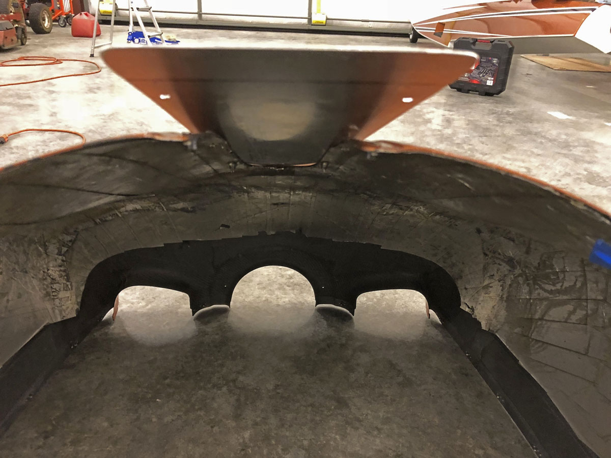
Ted wasn’t satisfied with his lip, so when he was helping to build Tom Needham’s second Sportsman for rough duty in Cameroon, Africa, he decided to split the bottom cowl and drastically widen the exit hole. Based on my testing, it seemed to me that Ted had the right idea, so I set about to prove the theory to myself. I replaced the plate I had made to cover the nose gear hole with a new one. This time, instead of the sides of the plate being parallel to each other (thereby just fitting the hole they were originally intended to cover) I angled the sides outward toward the back by a full inch (half inch per side). In this way, when the six mounting screws were put into their respective nutplates installed on the lower cowl, the cowl opening was forced apart causing the exit hole to expand dramatically, more than doubling its original size. The plate was also lengthened to approximately 1.5” longer than needed to cover the hole. The excess length was bent down a full 90° (a sharper angle than Dennis’ lip and a much smaller width, but a lip nevertheless). Test flight results were amazing, with pressure differential showing 4.3” at 80 KIAS! That means my cooling airflow was effectively moving through the cowl at about 78 knots or nearly 100% efficiency. I knew I had the answer! I should mention that none of these mods had any detrimental effect on cruise speeds. I attribute this to the notion that although I was introducing additional drag at the bottom of the cowling, I was removing drag cause at the air inlets where air was refused entry due to the constriction at the exit.
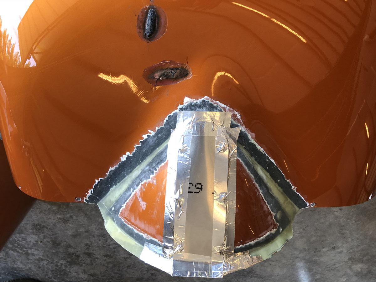
There was just one problem associated with my expansion plate. During flight, when the cowling was heated by the engine and being pushed by the oncoming air, the stress placed on the cowl pulling down on the trailing edge of the nose gear hole caused the lower cowling to buckle upward toward the engine about midway, right into the place where the exhaust pipes come closest to the cowling. Can you say melted carbon fiber? Ouch. Not a huge problem, since we were about to cut into that pretty paint job anyway, but as I pushed the plane back into the hangar and saw my paint bubbling before my eyes, it definitely got my attention!
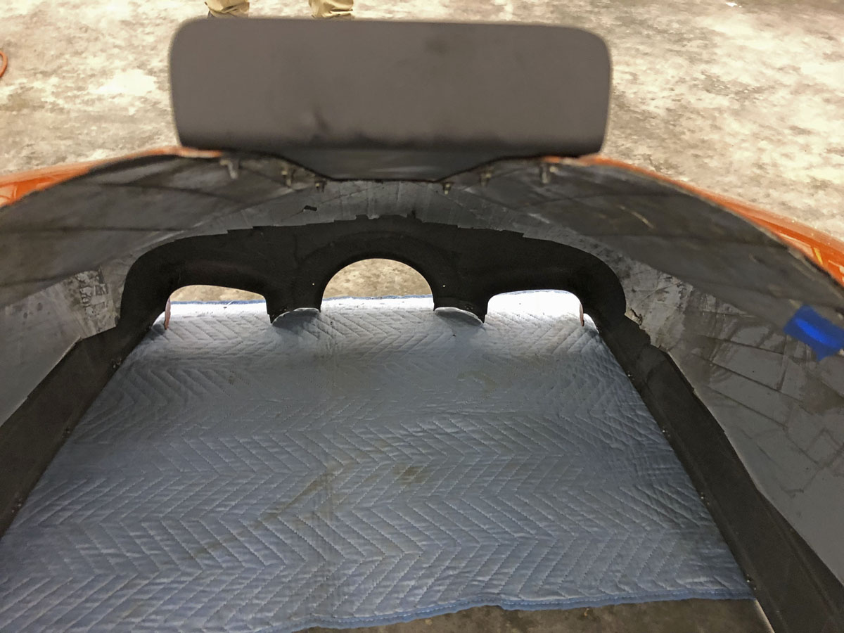
So, with concept proven, we cut into the cowl to expand the exit hole and we laminated a lip (at about a 30° angle following Dennis) to the entire newly expanded exit hole. Final testing was done with the modified cowl, straight (parallel) sided plate and no spacers, which resulted in similar results but without the propensity to collapse the cowl into the exhaust. Another frequent Glasair Forum poster, Chris Wills, has added electric cowl flaps (from Anti-splat Aero) to his lower cowl and I considered that as well but didn’t want to have an electrical connection between the airframe and cowl to have to disconnect and reconnect each time the cowl was removed/replaced. If I needed additional cooling, I’d add those cowl flaps, but I would build a frame to mount the cowl flaps to the airframe the way they are mounted to my Mooney. Fortunately, that won’t be necessary.
During testing with the angled plate, at a sustained max power climb of 80 KIAS departing a runway in eastern Washington at 400 MSL, OAT of 91°, second flight of the day (hot engine) I saw my oil temp slowly climb to a peak of 215° at 4300 feet, then start falling (due to reduced ambient pressure and temperatures) and it was down to 202° at 6500 feet where I leveled off and reduced RPMs to 2600 (but did not reduce MAP). Ten minutes later the oil temperature was stabilized at 189°.
Prior to my modifications, oil temperature would rise rapidly, and almost refuse to cool. When I had Dennis’ lip installed and half inch spacers and the original cover plate, on a 78° day in Arlington, my oil got to 235° before reaching 3000 feet, so I took evasive action, lowering the nose and reducing power. Most of you won’t have the issues to the degree that I’ve seen because your airspeed at cruise is much higher on wheels than they are on floats, so you have much better cooling air flow once you level off. But if you want to improve your cooling efficiency (whether concerned with oil temp or CHTs) and without compromising cruise speed, consider expanding your exit hole and adding a lip to disrupt the airflow coming down the lower cowl. I’ve spoken with Nigel Mott, president of Glasair, and he’s considering modifying their cowling molds to expand the opening and add the lip. Who knows? They may even come up with a retrofit kit.
Did the cooling ramps help? We don’t know. It’s possible that we could have gotten the same results without the cooling ramps, but maybe not. To know for sure, someone would have to modify their lower cowl without the cooling ramps in the upper cowling, measure their differential pressure, then add the ramps and test again. So, if you’re thinking of doing my cowling mod, I’d suggest you do that first, and add ramps only if necessary, (and maybe ultimately followed by cowl flaps?).