Although I have greatly enjoyed my Sportsman’s amphibious floats (Clamar 2500’s) over the past 9 years, there have been a few issues that have evidenced themselves on numerous occasions. I’ve previously written about the changes made to my float rigging when I replaced my original smooth bottom floats in 2017 with the new and improved fluted bottoms. Last year, my rigging changes were adopted by Clamar, as they have greatly enhanced takeoff performance and, together with the fluted bottoms, eliminated the problem of the floats sticking to the surface in glassy water conditions; but the new floats came with water rudders that were inferior to the originals, and I felt that even the originals were somewhat inadequate for an aircraft with a gross weight of 2650 pounds.
The rudders on both the smooth bottom and fluted bottom floats have always seemed too small, requiring plow turns whenever surface winds exceeded about 6 knots. Plow turns are risky maneuvers requiring high power and high deck angle at low speeds, inviting high engine temperatures and putting the plane in an unstable attitude which, coupled with the rough water conditions caused by surface winds, can cause damage to the airframe, engine and propeller. That was something I just put up with for several years, but during a “rough water” event last summer, one of the rudder blades bent, so needing a new rudder anyway, I set about to improve the design.
During the short flight that bent the blade, I had another Clamar owner aboard. He was interested in seeing my new float rigging in action, as he was considering changing his rigging too. The water was a bit rough, due to numerous boat wakes on a beautiful Seattle summer weekend. I taxied up the boat ramp at his lakefront home, parked in front of his hangar, and he spent some time comparing my rigging to his. We then boarded the plane, taxied down the ramp, and deployed the water rudders when we had floated clear of the ramp. Passing the marker buoys, I set takeoff flaps, kicked left rudder to point us toward a suitable takeoff direction, then retracted the water rudders and advanced the throttle. Winds were very light, but boat traffic was heavy. We bounced off a couple of boat wakes and were flying in just a few seconds. My friend was amazed at the short takeoff run afforded by my new rigging. We climbed to about 500 feet AGL, then turned around and landed opposite the direction we took off. After the plane quickly decelerated on the water, I deployed the water rudders once again and taxied back to his house, then retracted the rudders upon reaching the ramp. Upon exiting the plane, my friend immediately noticed the severely distorted blade, as it had bent about 60 degrees near its middle. He couldn’t believe what he saw, because he admitted that he often inadvertently leaves his rudders deployed for takeoffs and landings with no ill effects, and mine bent even though it was retracted. We’re not sure if the blade was bent during the takeoff or landing, as neither seemed out of the ordinary. But, until that day, I hadn’t realized that Clamar had changed rudder blades from the much more robust 1/8” thick aluminum (0.125”) on my friend’s floats (and my original floats) to thinner 0.090” aluminum on the fluted bottom floats. What a difference a few thousandths makes!
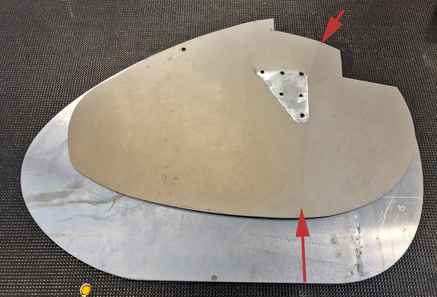
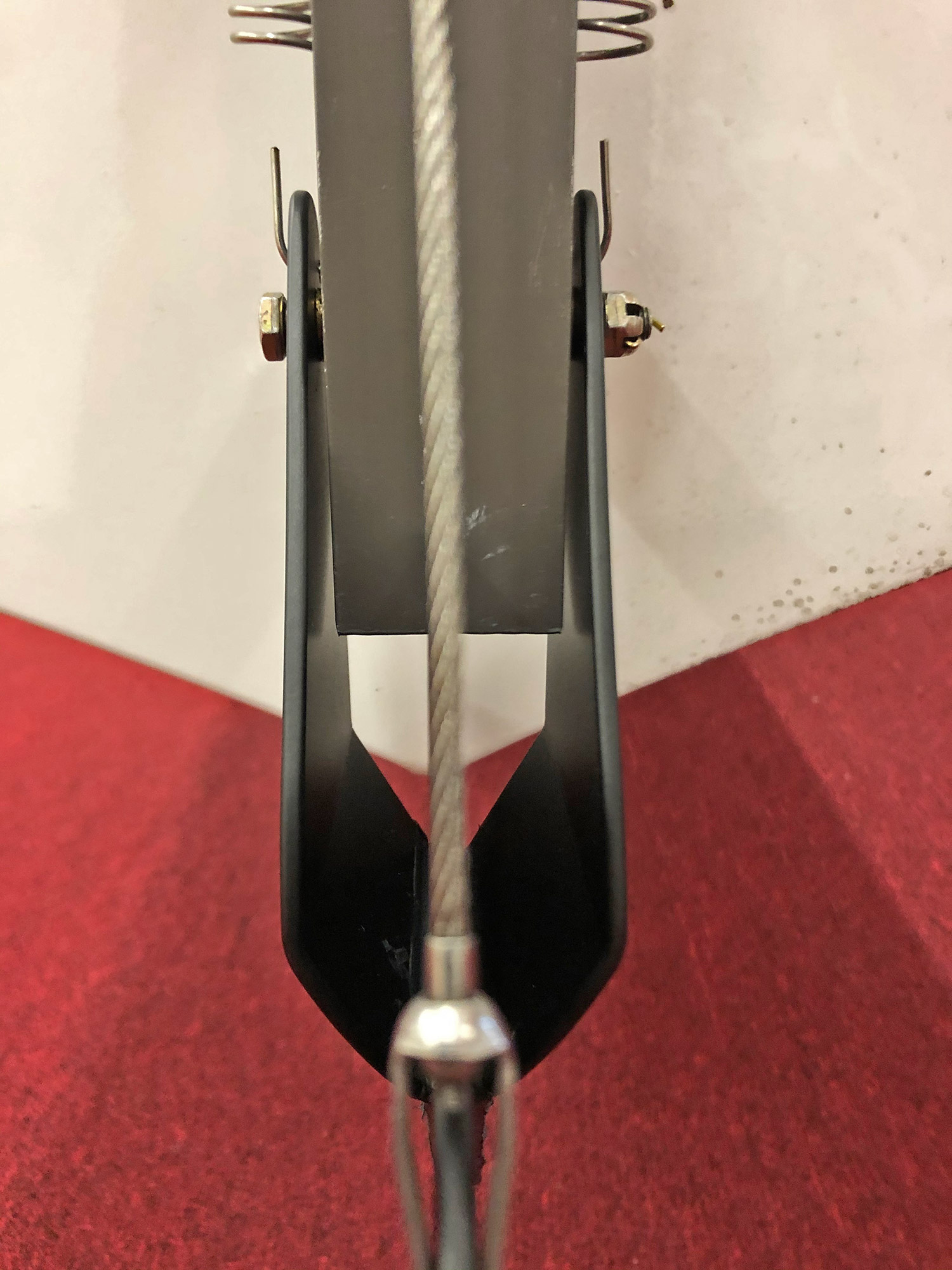
The next day, I borrowed my old water rudders from Glasair founder Ted Setzer to keep from being grounded (he bought my old floats but isn’t currently using them). I then drilled out the rivets that hold the attachment brackets to the bent blade and was further enlightened as to the deficiencies of the rudders. In addition to the blades being made of thinner aluminum, I saw that the brackets and blade had been riveted together prior to anodizing the assembly, leaving large patches of untreated metal between the brackets and blade. Additionally, the brackets had been formed by bending them in the wrong place which was evidenced by scoring on the inside of the brackets where, during extension and retraction, they were rubbing on the vertical square tubing that is attached to the rudder cables which are used to move (steer) the water rudders. So, now I had a list of improvements to accomplish (stronger material, larger blades, proper bracket angle placement & improved metal protection).
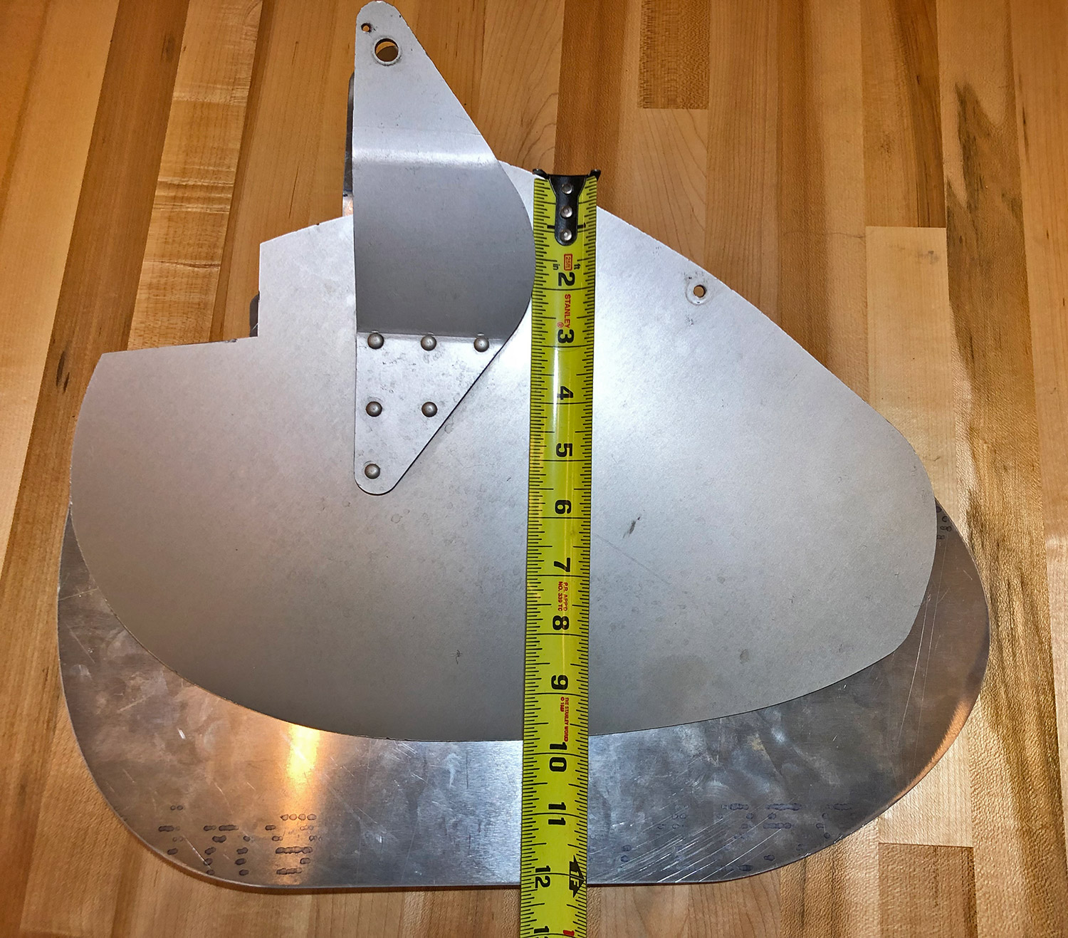
There are many considerations to water rudder blade design. Various parameters include material (weight, strength, corrosion resistance), shape, ground clearance, bending moments created by hydraulic pressure when steering, length vs. height, etc. For example, blades that are very short in height but long in length could easily be bent by hydraulic pressure, whereas blades that are very short in length would require excessive height to be effective for steering which would means they would afford little, if any, ground clearance. So, water rudders on floats tend to be reasonably balanced in relation to their height versus length. Looking at my blades, it was clear that I had room to make them larger in both directions, but favoring greater height over length, because they were already longer than they were tall. Clamar uses a common aluminum alloy for their water rudders (6061-T6). I suspect they changed to the thinner blades to save weight, but when they made the change to thinner blades, it may have been better to switch to another alloy like 5052-T3, as it is much stronger; however, it is more susceptible to corrosion than the 6061. I considered increasing the strength of the thinner blades by using the stronger 5052 in 0.090” thickness rather going back to the tried and true 6061 in 0.125” thickness, but ultimately decided not to use the 5052 due to its higher propensity to corrode.
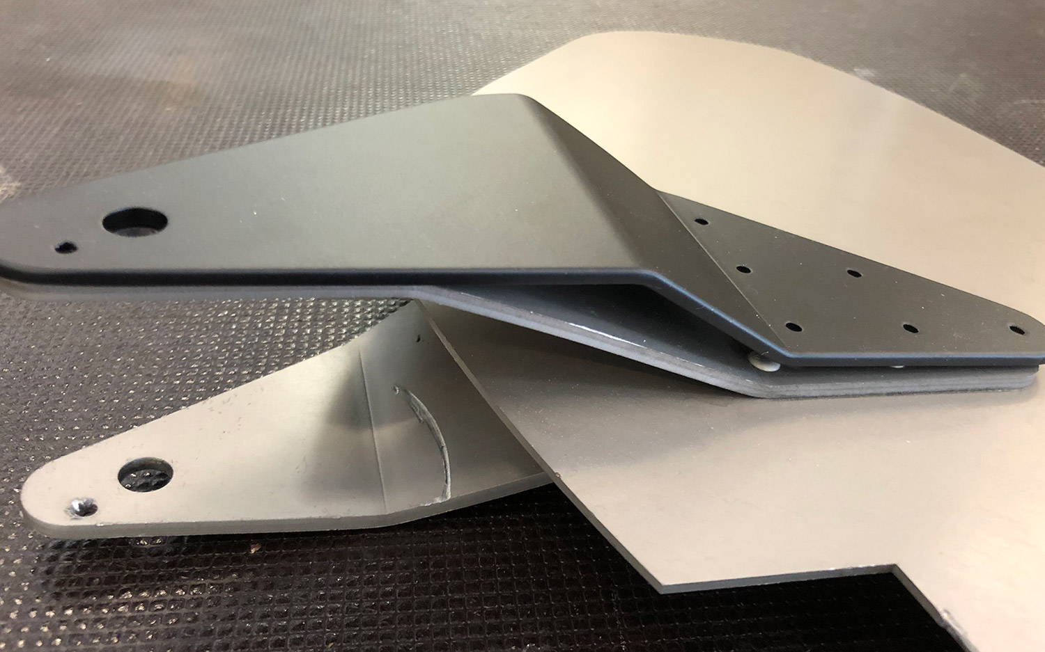
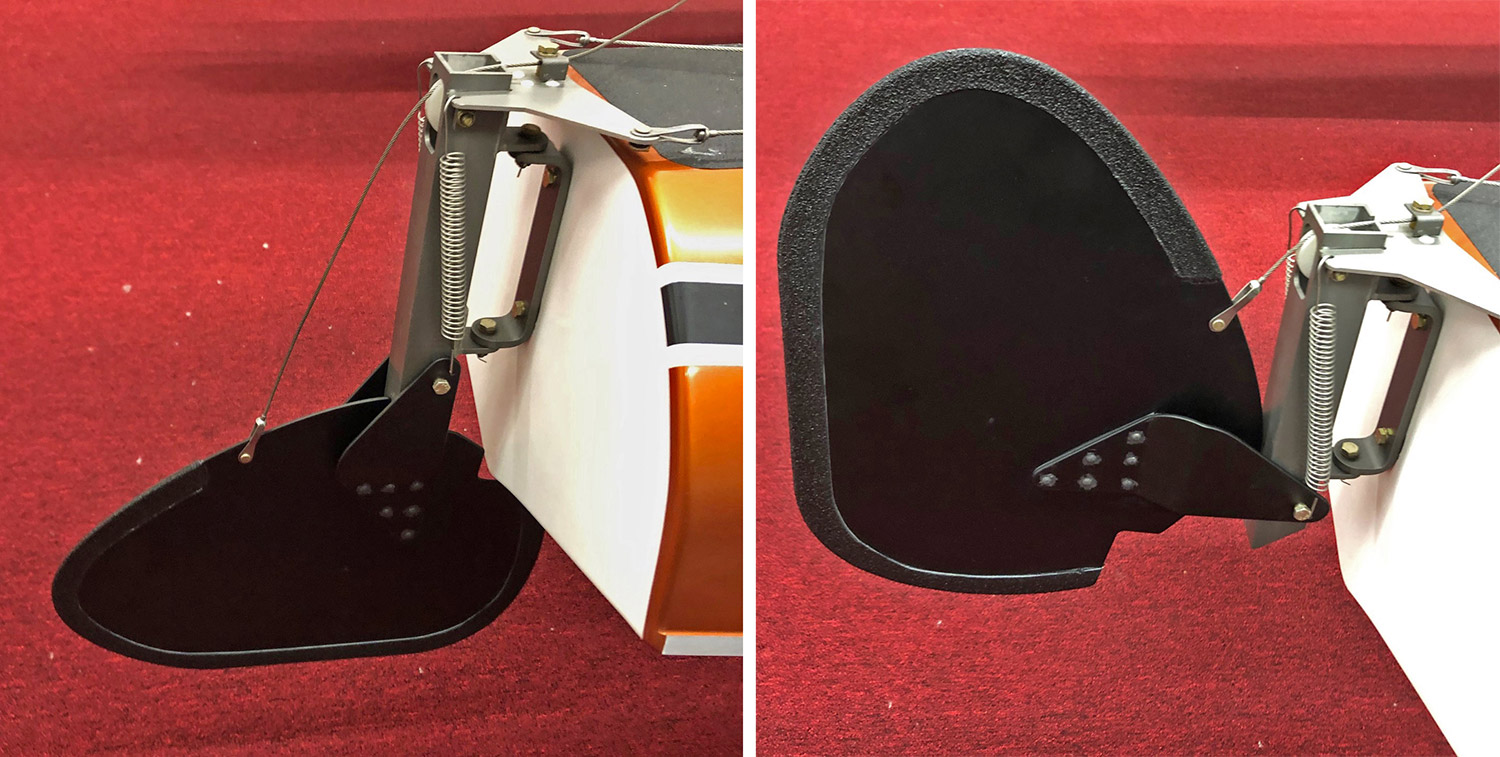
I sketched some new blade designs on cardboard and cut them out to “trial fit” them on the floats. I also sketched the brackets, primarily to reflect the “proper” bend positions, essentially duplicating the old Clamar bracket design evidenced by Ted’s rudders which did not have the fitment and scoring problems. When I was satisfied with the design of blade and bracket I took them to a friend who scanned them into SolidWorks so they could be cut by water jet. The new larger blades are a bit heavier than the originals due to their larger size, but the extra weight is exactly where you want it on a floatplane, near the back to help move the Center of Gravity (CG) aft a bit (planes on floats tend to have more forward CG than the same plane on wheels because the nose of the floats is forward of the propeller spinner). The new brackets were carefully bent into shape, then riveted to the new blades for testing.
We found the new rudders work significantly better than the old ones, allowing full steering authority on a windy day (12 knots gusting 15) so I may never do a plow turn again! And in light winds, they cause the plane to turn in a complete circle 40% faster than the old rudders. It was very helpful to have Ted’s rudders to test against my new design, since swapping them to test in identical conditions takes just a few minutes. Most testing was done on Lake Goodwin and Big Lake, each just a few minute flight from the Arlington, WA airport, home of Glasair Aviation. Lake Goodwin sits on a broad plateau where light winds prevail, whereas Big Lake sits in a valley that funnels wind down the lake due to the Venturi effect of the terrain. The two lakes gave us everything we needed to test varied weather conditions. We would test one set of rudders on a lake, fly back to Arlington, swap rudders, and a few minutes later we were back at the same lake testing the other set.
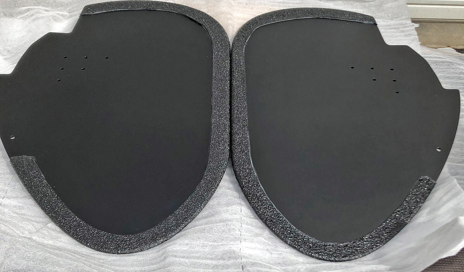
Once satisfied with the design, I set about to improve the metal protection. The rivets were drilled out to separate blades from brackets. Then, all the metal parts were thoroughly scuffed with Scotchbrite pads, cleaned with acetone and acid-etched to a gleaming “brand new” aluminum look, then Alodined. The local powder coater took it from there, applying a flat black powder coating to all the parts. I could have riveted them back together at that point and hung them on the plane, but I wanted to do one more thing to protect the blades. Float planes typically are beached tail first. When sitting on the beach. Waves rock the front of the floats causing the water rudders to move up and down in the sand, effectively sanding off their finish, be it paint, anodizing, or even durable powder coating. So I took the blades to the local spray-in truck bed liner shop and had them treat the edge of the blades with about a 3/4” wide application of RhinoLiner. That material should hold up well against sand, so I’m hopeful my new water rudders will last “forever.” The last steps were to rivet them together, apply a bit of black silicone to the seam between the blades and brackets as well as to the rivet heads/tails and hang them on the floats.
On a phone call with Clamar owner Paul Richards a few weeks ago, he told me about a customer who wanted bigger water rudders so the customer designed an add-on attachment, which Clamar improved upon and built for him. Paul bought Clamar about three years ago and seems genuinely interested in improving the Clamar products. When I told him what I had done and sent him pictures of the new rudders, he thought it to be superior to the add-on design and asked for my design. I sent him the SolidWorks file and he indicated that they were going to use it, as well as go back to 1/8” material, to build all future rudders in accordance with my design. He also liked the powder coating idea and will likely incorporate that too. New rudders should be available from Clamar soon. If you have floats built in the past few years using the 0.090” rudders, or if you’re tired of having poor steering capability with any Clamar 2500 floats regardless of build date, you may want to pick up a new set of rudders from Paul, or make your own like I did.


