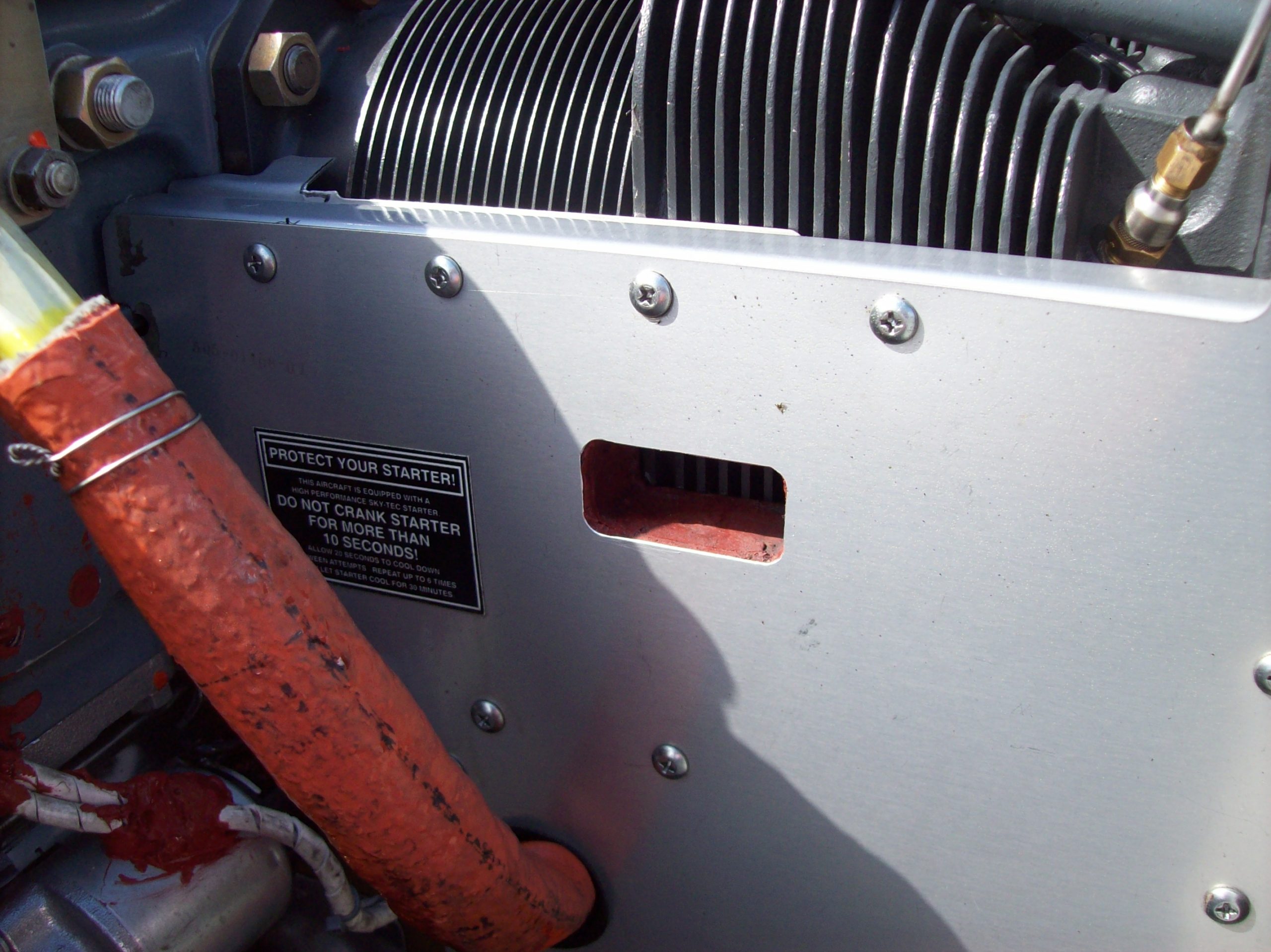
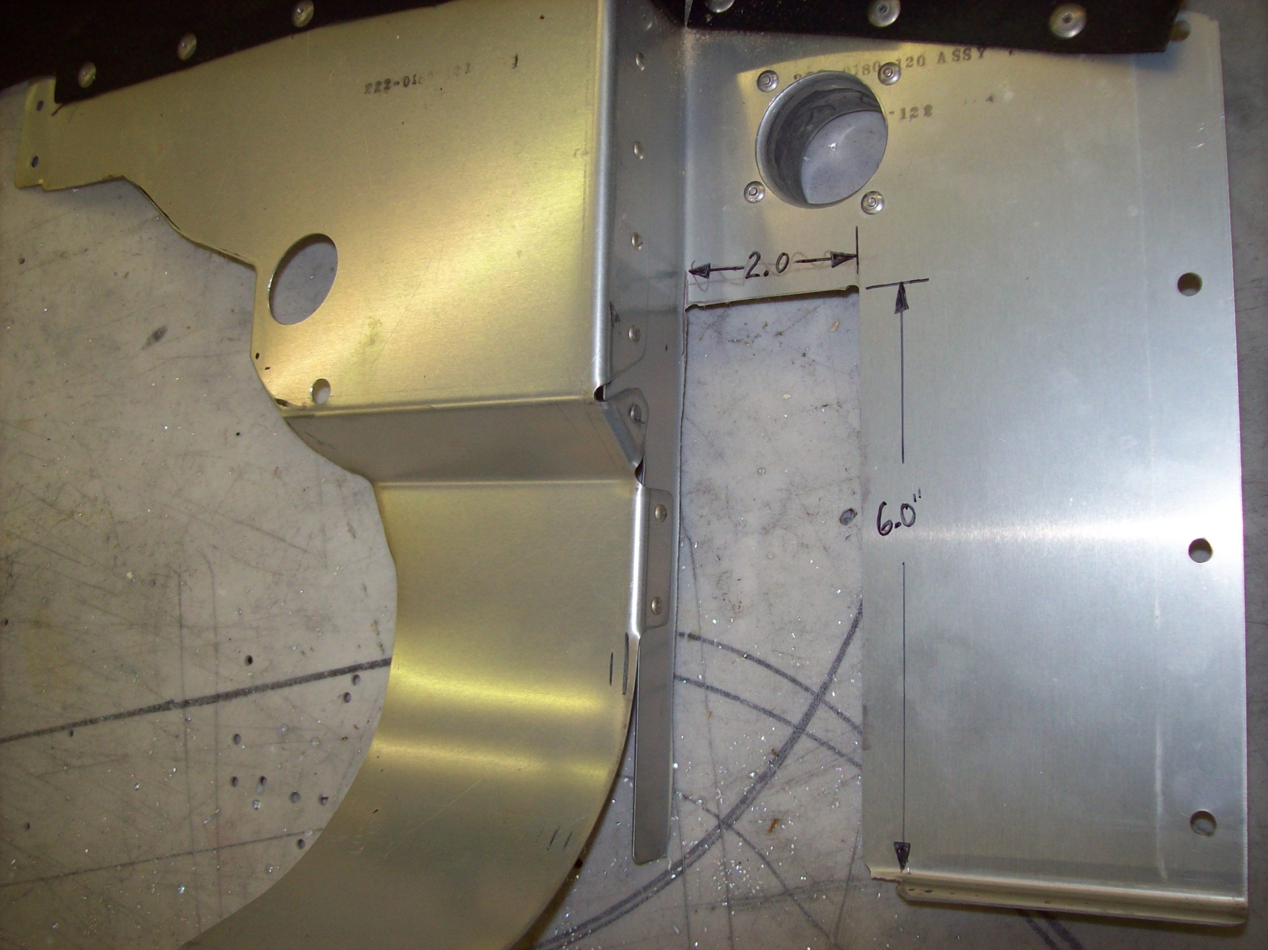
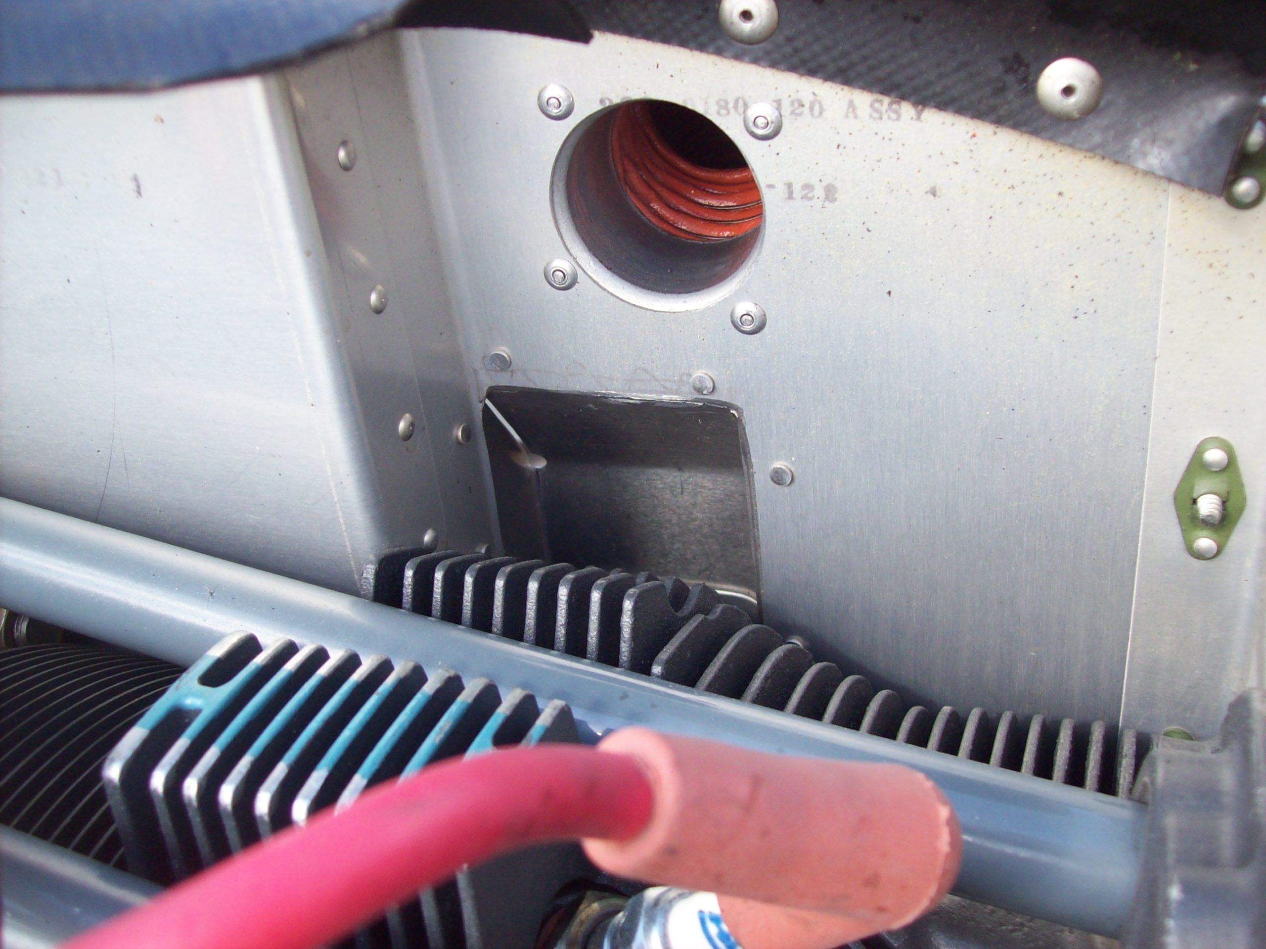
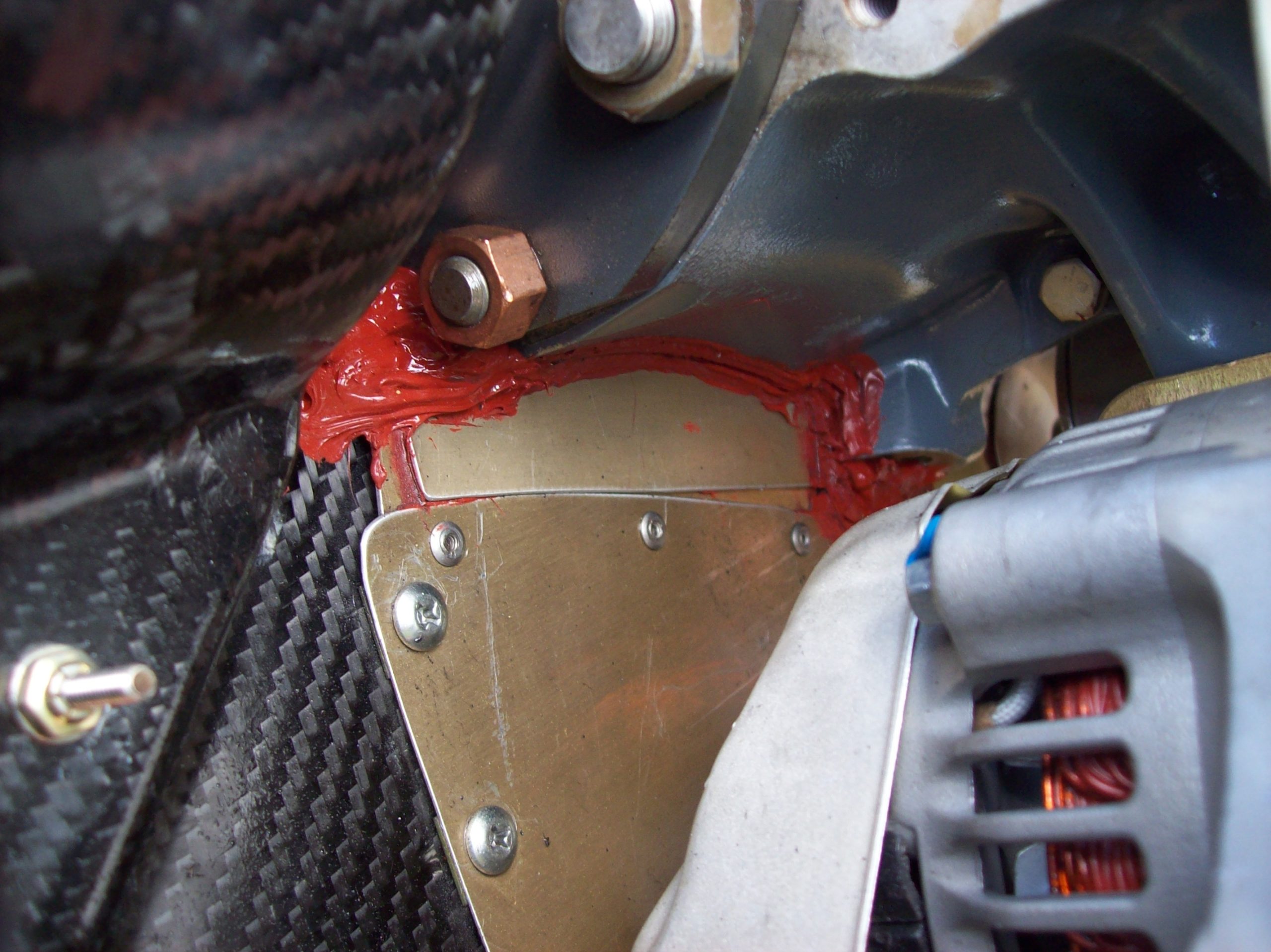
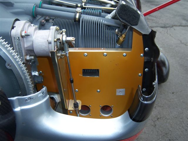
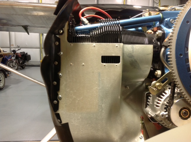
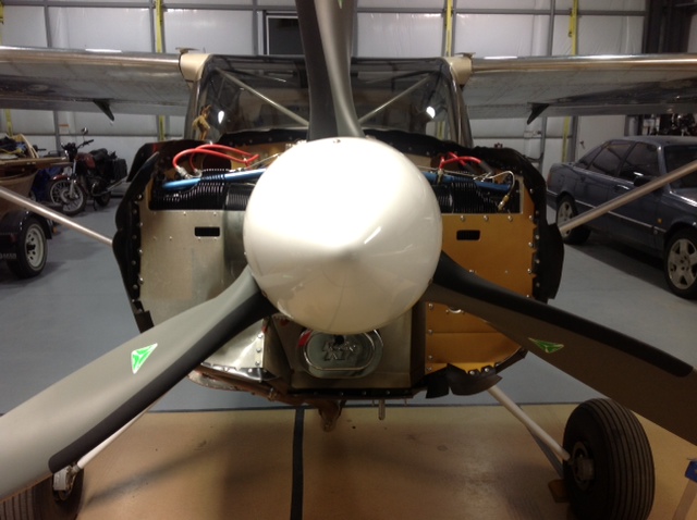
This is a technical tip for the cylinder baffling modifications we’ve come up with for the IO-360 and IO-375 engines. The windows in front cylinders #1 and #2 drop cylinder temperatures by approximately 30 degrees. They are placed over the deep fins below the mid-line of the cylinders which are approximately 2.0” wide. The windows allow cooling air to enter the fins on the lower front portions of the cylinders. They are 1” tall x 2” wide. Cylinder #1 is relatively easy to do since it is a flat laminate backed with aluminum baffle. A few extra rivets may need to be placed once the window is cut. Cylinder #2 is a bit more challenging since it is a double wall baffle with 5/8 -3/4” air space between. I accomplish this by cutting the windows in both aluminum pieces, then placing foam core between the aluminum pieces and bonding it with silicone. I sand the foam back approx 1/16” from the window opening edges after it is in place between the aluminum and coat the exposed foam inside the opening with high temp silicone (finger wipe). I haven’t tried it yet, but I think if the window in cylinder #2 was even wider on the front side say, 2” tall x 3” wide forming a funnel down to the 1” x 2” dimension on the aft piece, it would improve cooling since I didn’t see as much temperature lowering on the #2 cylinder window as we did on the #1 cylinder window. (20° vs. 30°).
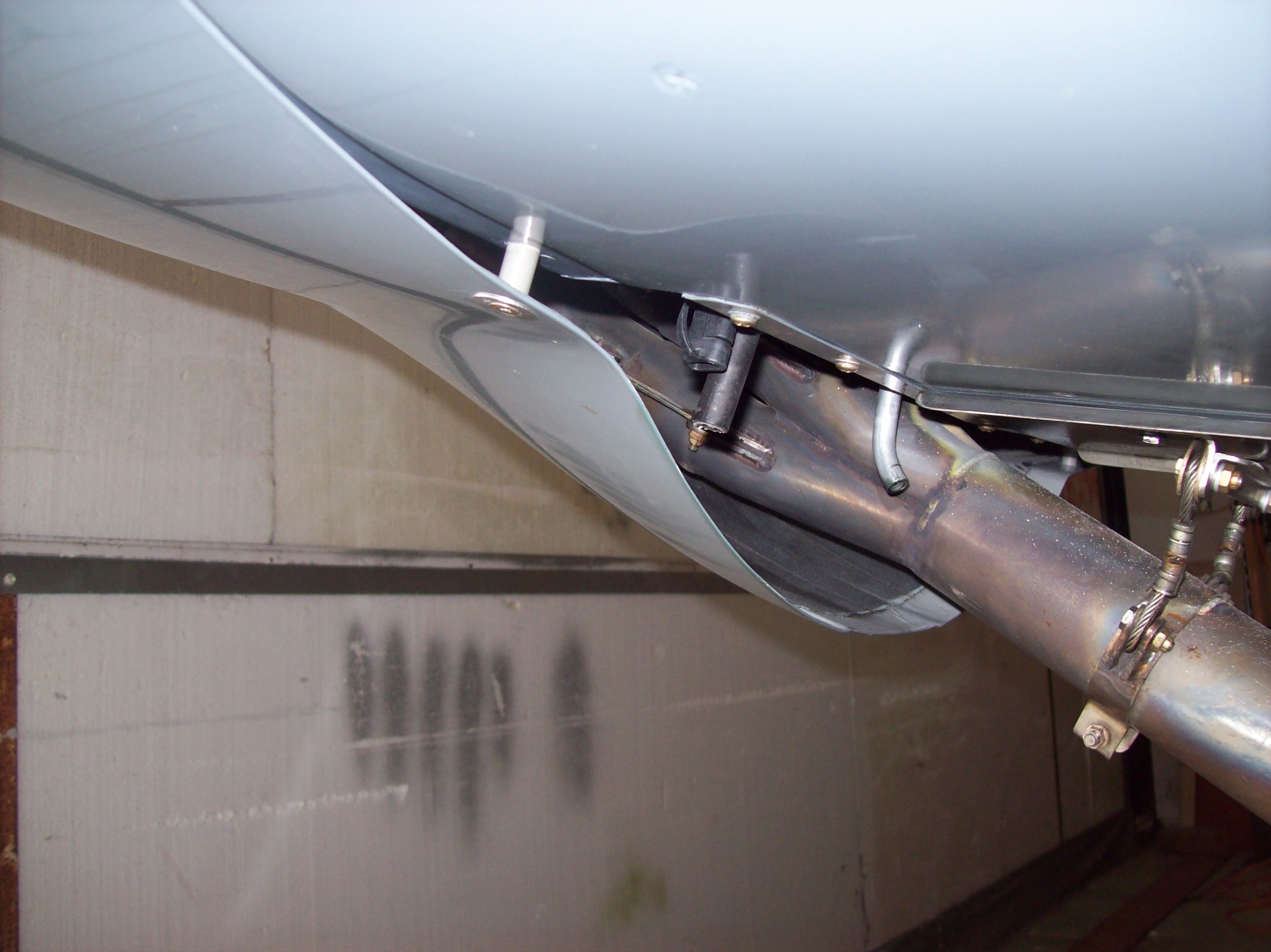
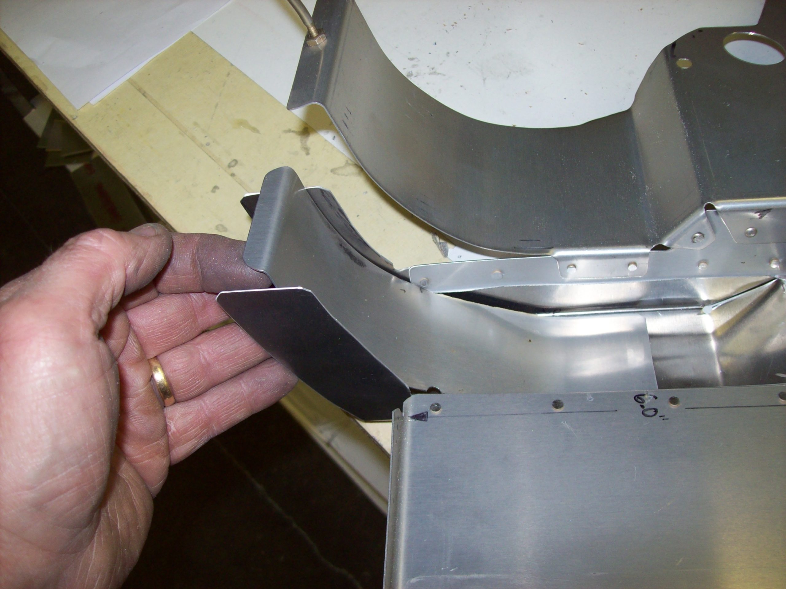
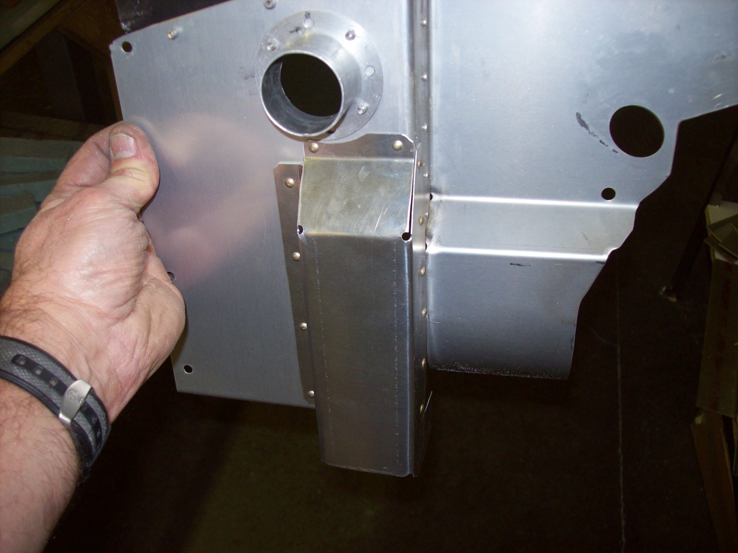
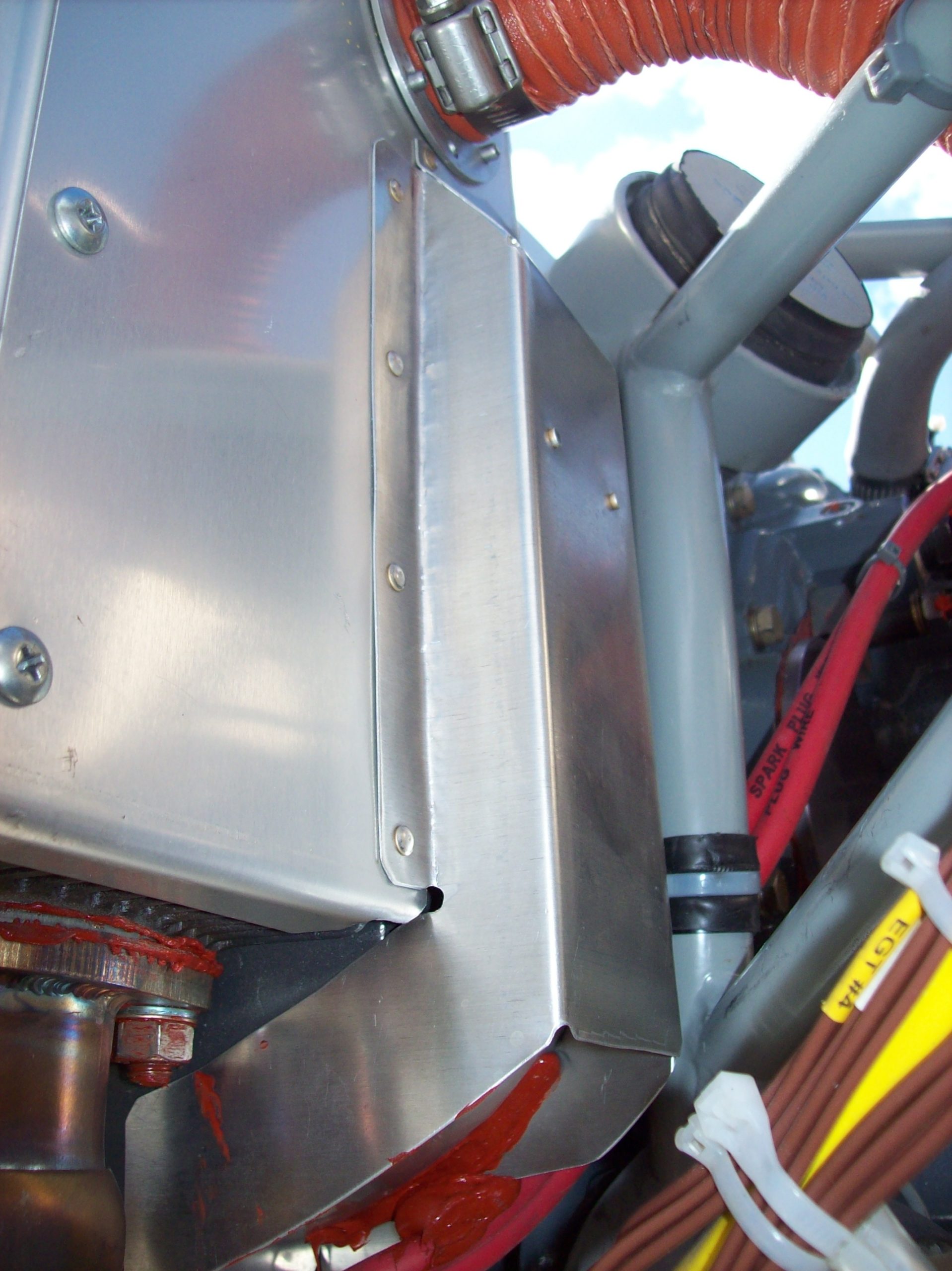
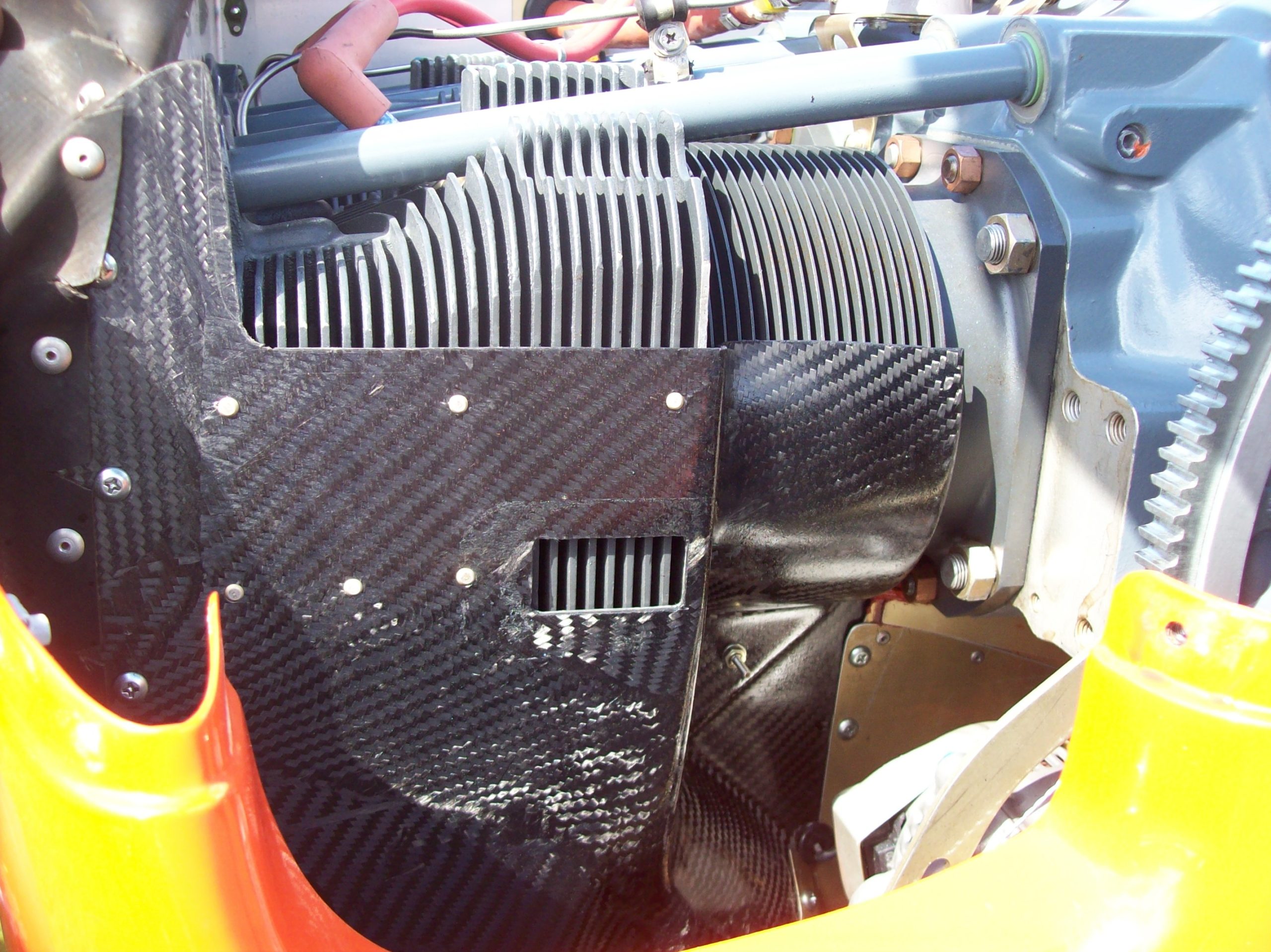
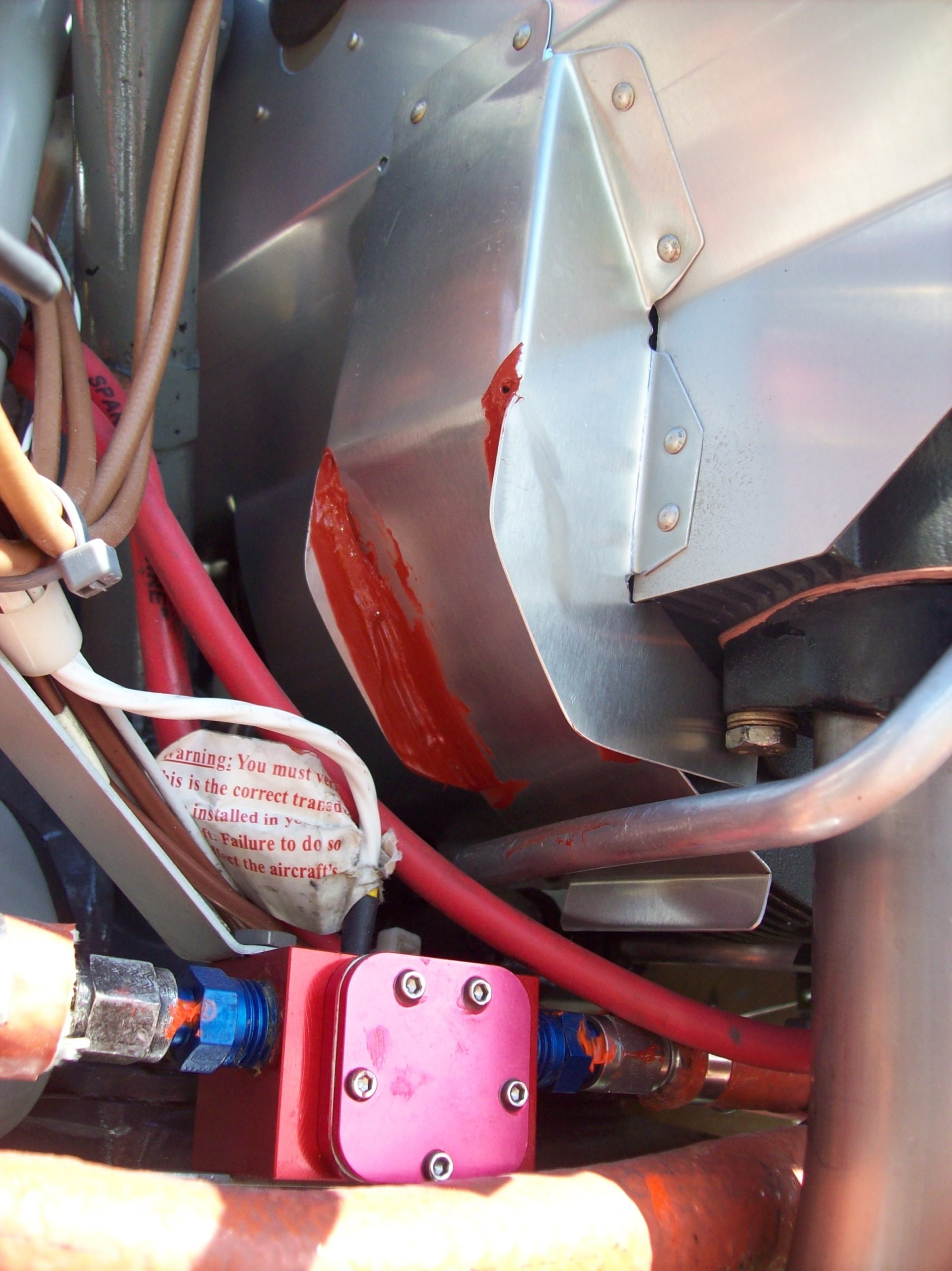
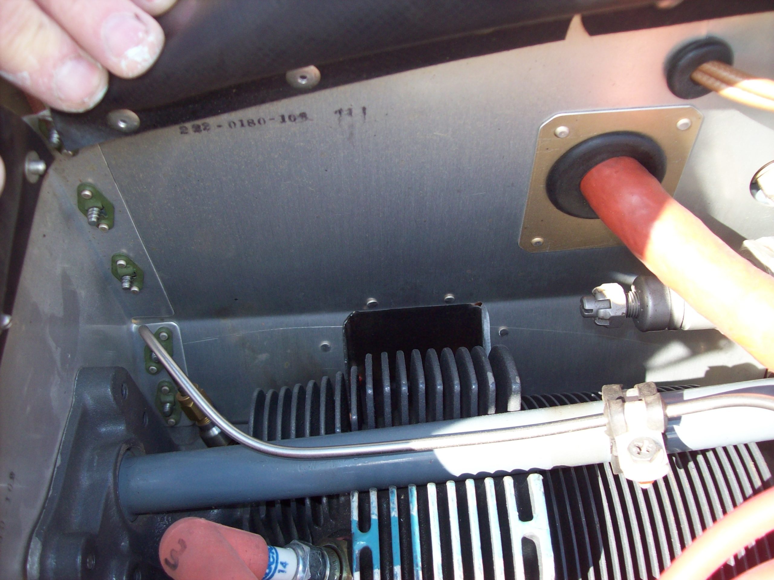
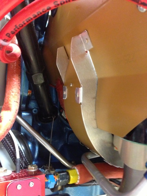
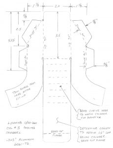
To get similar cooling air beneath aft cylinders #3 and #4, aluminum channels must be fabricated and placed behind the aft baffle pieces. These channels are riveted to the aft baffle pieces after they have been notched out as seen in the photos.
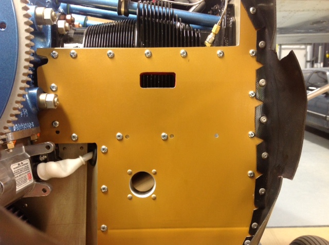
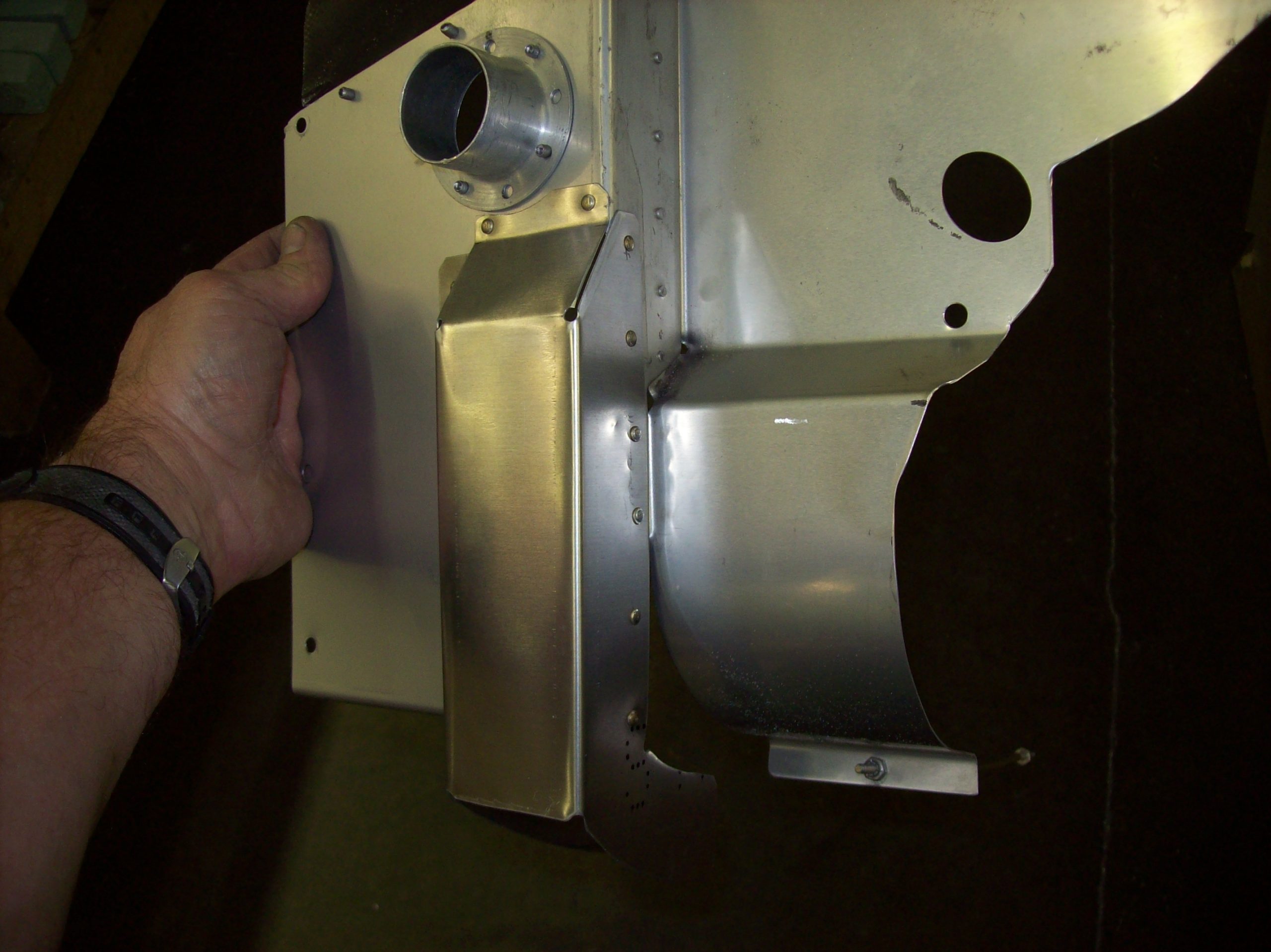

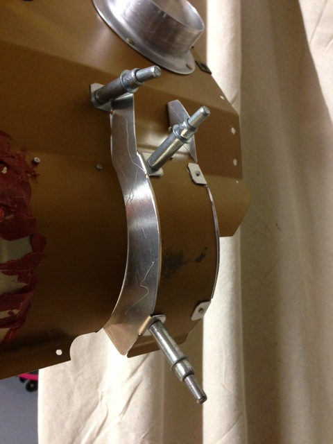

I made templates off of the channels I fabricated on my IO-375 and they can be downloaded from the Glastarnet website.
Sportsman builder Peter Kline tried out these baffle modifications and reported as good or better results than I recorded.
One other tip: I discovered that the curved baffles that form under the cylinders need to be tight against the fins not allowing air to escape out the sides. But, at the bottom of the cylinders, make sure there is a 1.5-2.0”-wide gap between the curved baffles to allow the air to escape out he bottom and not “dam up”.
IO-390 engines do not need these as they have oil nozzles that squirt engine oil at the back-sides of the pistons essentially lowering cylinder head temperatures very effectively. The “payback” on the 390 engines is that they have—as one would guess—elevated oil temperatures requiring a larger oil cooler.
Another way to increase air flow through the cowling for both IO-390 and -360 installations to help with both cylinder head temperature and oil cooling is to place a 3/4”-long aluminum spacer bushing between the cowling and the joggle flange on the most inboard screws on the lower cowl to open up the exit area. Just use a longer AN509 or AN507 machine screw.
Hardware needed:
(2) AN 50910R22 machine screws $0.50 ea
(2) NAS43DD4-50 aluminum spacer bushings $2.28 ea
(2) 371-5101-003 countersunk stainless steel washers $0.40 ea