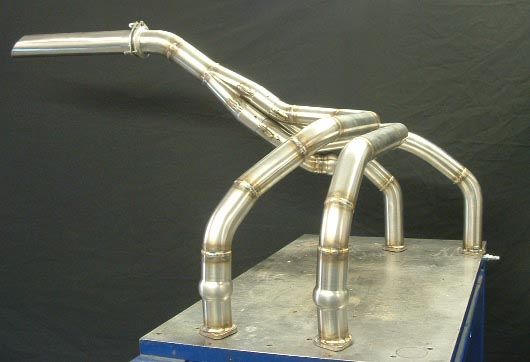
The installation and inspection of your aircraft’s exhaust system are fairly straightforward subjects, but we get enough queries from both Glasair and GlaStar builders to suggest that a few tips and pointers might be useful. Although the exhaust systems used on Glasairs and GlaStars with different engines have differences in shape and style, most aspects of their installation and inspection are identical.

The principal purpose of the exhaust system is to route combustion gasses exiting the engine cylinders clear of the aircraft. Along with the exhaust gases leaving the cylinders, a substantial amount of heat is being conducted away from the engine. S-H exhaust systems trap some of this heat in a special heat muff to provide cabin heat and, in the case of carbureted engines, carb heat. The downside of the heat is the effect it has within the engine compartment; this will be discussed later.
Installation Tips
The typical exhaust system installation will require the pipes themselves; an exhaust gasket to seal the joint between the exhaust system and the engine cylinder; and the nuts, washers and lock washers needed to secure the exhaust system to the threaded engine studs.
Always begin by carefully removing any surface corrosion from the aluminum seat around the cylinder exhaust port. For very light corrosion, use ScotchBrite and a metal cleaner like PrepSol. Do not use steel wool. Fine sandpaper can be used for heavier corrosion. Sand until a clean aluminum surface can be seen. Some small amount of pitting is allowable. However, serious corrosion or other major damage to the cylinder seat may require the use of a special exhaust seat grinding tool. Bad seats cause exhaust leaks, with the serious consequences discussed below, so if you’re in doubt about the condition of any of the seats on your engine, have your local A&P mechanic take a look.
Just as the seats must be clean and flat, the mounting flange on each exhaust pipe must be clean and flat too. Before reinstalling an exhaust system that has been in service, check the surface of each mounting flange. Flanges that are corroded or not flat can be fixed by touching them to a belt or disk sander. Any low spots on the flange will clearly show as unmarked areas. Continue sanding until an even, flat, round area is available around the pipe on each flange. It is also a good practice to use a hammer to tap the corners of each flange where the bolt holes are slightly downward. This way, as the nut holding the exhaust pipe to the cylinder stud is tightened, the sealing surface of the exhaust pipe flange contacts the exhaust gasket before the flange corners.
Several types of exhaust gaskets are available—two-piece copper gaskets, copper/asbestos gaskets and the so-called “Blo-Proof” steel gasket. We have found the latter style best for our exhaust system installations. We have had good success with these gaskets, finding their thickness and rigidity to work well at sealing and preventing exhaust gas pressure from blowing out the sides of the gasket.
We have also found that coating both sides of the exhaust gasket with red, high-temperature silicone sealer (RTV) (available from your local auto parts store) great improves the sealing qualities of the installed gasket. This material will dry and harden in a relatively short time, so it should only be applied immediately before installation.
Regardless of the style used, keep in mind that exhaust gaskets are not designed to be reused.
The hardware used to secure the exhaust system must be capable of withstanding the high heat of the cylinder. We use standard, AN960-516 steel washers, and we recommend an AN935-516 split lock washer, although we have often used the more common AN936A516 internal-teeth lock washer. The exhaust system mounting studs on the engine are coarse threaded. Plain nuts are used to hold the exhaust system in place. Lycoming uses a steel nut for this application.
Due to heat in this area, the engine stud, washers and nut will all rapidly develop a coating of rust. This rust tends to lock the nut in its tightened position. When removing a nut that has been installed for some time, it may be helpful first to use a small wire brush to remove surface rust from the cylinder stud.
All S-H exhaust systems incorporate slip joints to allow for slight movement and to facilitate fit-up. The theory of the slip joint is that the inner tube of the joint will be hotter and expand more than the cooler, outer tube. This uneven expansion then creates a seal, preventing exhaust leaks. Slip joints will often use a securing method between the two tubes of the joint. Glasair exhaust system collectors have a spring holding the collector to the engine pipes. The GlaStar systems have a two part clamp which extends over the joint and uses four bolts to hold the two clamp halves firmly together.
When a bolt and nut are used to secure the two halves of a slip joint, use steel, self-locking AN363-1032 nuts. These nuts and the bolts will also soon become rusted in color, and the nuts should not be reused once loosened.
For the easiest installation, don’t tighten any of the exhaust securing nuts until all parts of the exhaust system have be slipped into place. On the Glasair, this means the exhaust collector should be slipped over the two tubes flowing into it. On the GlaStar, this means the collector should be slipped onto all four of the stub pipes exiting the cylinders. Once this has been accomplished all nuts should be properly torqued.
Precautions for Components Installed Near the Exhaust System
Heat radiating from the exhaust pipes can cause premature aging and hardening of rubber and plastic components exposed to this heat. Because of the confines of the engine compartment, the builder must deal with this reality and plan the location of the wire runs, wire-securing parts, hoses and so on to minimize the effects of the heat.
Numerous wires are routed below the cylinders. Some wires, such as magneto wires and the leads for the EGT and CHT probes are designed to be resistant to the heat of the exhaust system. However, they still should be secured as far away from the exhaust pipes as is practical. A convenient route for these wires is inboard along the engine intake tubes and then aft just above the split line between the engine case and the oil sump. On many engines, it’s convenient to install one or two Adel clamps on the 1/4″ sump studs to secure these wires.
Occasionally it will be necessary to run oil lines or fuel lines near the exhaust system. When very close to an exhaust pipe (within about an inch) the hose should be enclosed in fire-sleeve for insulating purposes. All other rubber hoses should be routed as far as possible from the exhaust system.
Engine shock bushings are also subject to heat decay. When subjected to high heat, they will become hardened and heat checked. Given the geometry of the systems, this is more likely to be a problem on Glasairs than GlaStars. Fortunately, the problem can easily be solved by installing simple aluminum heat shields around the lower shock bushings.
The components most commonly used to bundle wires and provide anti-chafe protection are tie-wraps and spiral wrap. These are usually made of Nylon and are very subject to heat deterioration—embrittlement in the case of tie-wraps and melting in the case of ordinary spiral wrap. Spiral wrap, of course, comes in a high-temp variety, and this is all you should use in the engine compartment. It can be distinguished from ordinary spiral wrap by its pale blue tint. Tie Wraps are not available in a high-temperature variety, so care should be taken to use wider-than-usual wraps in the engine compartment and to inspect and replace them frequently.
In Glasair RG aircraft, the nose gear hydraulic actuator is located relatively close to the exhaust system. The nose gear cylinder is aluminum and will absorb and transfer heat to the hydraulic fluid in the cylinder. This heat causes the fluid to expand, increasing pressure in the system. The heat can also have a detrimental effect on the seals in the cylinder. For these reasons, an aluminum heat shield should be installed between the nose gear cylinder and the exhaust system. You should also inspect regularly for any evidence of hydraulic fluid leaking around the piston rod of the actuating cylinder. This could be an indicator of seal deterioration, and if severe enough, could suggest the need for a cylinder overhaul.
Inspecting the Exhaust System
One of the gases routed overboard by the exhaust system is carbon monoxide, and we all know how important it is to keep this out of the cabin. Some early warning signs of a possible exhaust leak are, of course, an exhaust smell in the cockpit, but also the presence of gray dust in the windshield defrost and cabin heat vents. Regardless of whether any of these signs is present, however, frequent inspection of the exhaust system (and in particular the cabin heat muff area) is very important.
An installed exhaust system should be inspected for four things: cracks in the exhaust system itself, leaks where the exhaust mounts to the cylinders, damage to or fatigue of the collector suspension system, and heat damage to surrounding fiberglass structures.
Cracking is most likely at pipe intersections and near weld joints. Cracking can also occur in slip joint areas (of exhaust systems using a slip joint at each cylinder) if the bolts holding the two halves are tightened unequally. Check for cracking by wiggling the pipes to detect any loose segments and also by looking for light gray exhaust residue on the pipes. If cracks are found, remove the affected pipes (or the whole system, as necessary) and take them to any competent welding shop. (Because of the welded nature of the exhaust system, there is likely to be some variation in the exact size and geometry of all exhaust system components. For this reason, it’s impractical for S-H to maintain an inventory of exhaust system spare parts.)
The automotive industry has used exhaust pipe wrapping materials for quite some time in special applications. We have not had the opportunity to try these materials so we have little first-hand experience, but customer reports have detailed lower temperatures within the engine compartment. However, if you use exhaust pipe wraps, greater care must be taken to inspect adequately the now-hidden exhaust pipes for cracking.
Leaks around the cylinder seat and/or exhaust mounting flange are indicated by the presence of gray dust on surrounding spark plugs, cylinder cooling fins and intake tubes. An exhaust leak here is very serious, not only because of the possible problem of CO entering the cabin, but also because the jet of leaking exhaust gas will very quickly erode the soft aluminum of the cylinder seat and surrounding cooling fins. If allowed to worsen undetected, this situation can eventually damage the cylinder beyond repair—not a pleasant thought.
Thus, any evidence of an exhaust leak at the cylinder must be dealt with immediately. This will involve removing the sections of the exhaust system necessary to get to the leaking cylinder. Any cylinder which has had a detectable leak should be inspected for seat damage.
On GlaStars, the exhaust system is compact enough that the exhaust collector is simply cantilevered off the stub pipes. On the Glasairs, however, the longer collector or collectors are suspended beneath the airframe by metal springs or brackets. Any failure of these suspension parts will almost certainly lead to cracking somewhere “upstream,” so a thorough exhaust system inspection will include these parts.
Finally, check the cowling, exhaust tunnel and other fiberglass parts close to the exhaust system for any discoloration. Check the inside, unfinished surfaces, as paint will hide this sort of damage. Some light tan-to-brown discoloration is not a cause for alarm. However, any dark brown-to-black or charred areas indicate the need for remedial action.
First, repair any badly damaged areas with new laminations. Then install one or more heat shields to protect these areas in the future. One good method is to use pieces of Interam 110 applied directly to the fiberglass. This material comes in sheets approximately 1/4″ thick. It can be bonded to fiberglass using high-temp RTV.


