Parts not supplied by S-TEC:
- Two pulleys MS 20219-4
- Two bolts AN 4-23 (to replace the existing forward aileron pulleys bolts)
Location of sub-assemblies
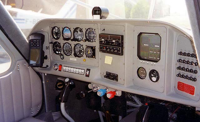
Turn coordinator/roll computer: replace the standard T/C on the instrument panel
Roll servo: under the copilot seat, positioned to obtain a satisfactory cable loop, taking into account the diameter of the pulleys, bolted to the floor (through the fuselage).
T/C to roll servo harness: routed along the transverse tube (lower edge of the instrument panel) to the right door post, then under the floor to the servo.
Pitch computer: S-TEC recommends putting it somewhere behind the instrument panel, presumably to get the out of trim piezo signal heard in the cabin. I did it differently for two reasons. First, this computer has to be installed horizontally, and this is not easy behind the instrument panel. Secondly, as I always wear an headset , I will not hear the piezo anyway.
I decided to install the pitch computer under the pilot seat, near the pitch servo, and to use the output supplied by S-TEC to drive an external optional piezo, to trigger a home made circuit generating a tone in my headset. I believe that S-H has installed this computer inside the copilot seat. It may not be easy to remove the seat.
The pitch computer is bolted to a glassed support which is blind riveted to the floor
Pitch servo: under the pilot seat, positioned to place the capstan and the cable right under the elevator lower cable.
Altitude transducer: attached with a small bracket to the cage tubes near the central upper forward node (the one with the higher engine mount bolt) in order to intercept approximately the highest section of the static line joining the static ports.
Pitch computer to T/C harness: routed across the central cage tube to rejoin the roll servo cable and then follow the same path to T/C.
Pitch computer to pitch servo: very short
Pitch computer to altitude transducer: follows the same route to door post , then follows the cage tube joining the upper node.
A/P Disconnect: I have located this push button on the left ear of the pilot military style stick grip.
Altitude Hold: I have located this push button on the right ear of the pilot stick grip.
Caution! To position the servos, you have to install the cables on the capstan and remove the cable guards. Be cautious when replacing and tightening these cable guards as they are fragile and make sure that the capstan does not rub inside the cable guard cap. You may have to insert washers to achieve this. It is better to do this before installing the servos on their brackets.
Length of the cables (on my installation)
With reference to drawing # 39188:
- Item 8 Roll servo: 100″
- Item 9 Directional gyro: 12″
- Item 10 Vor/Loc, Rheostat: 30″
- Items 11(A+), 7 (Gnd), 10 (A/P disc): 72″
With reference to drawing #39189:
- Item 4 Transducer cable: 112″ (approximately)
- Item 5 Pitch interface: 125″, (from the pitch computer to the plug of the T/C-Roll computer plus 30 inches for wires red ( A/P A+ )and black (Rheostat) ,as they have to be routed from the T/C plug to the A/P switch and to the rheostat bus.
- Item 6 Pitch Servo: 15″
- Item 3 Altitude Switch: 20″
- Item 9 Piezo Alarm: 15″
- Item 10 Ground Wire: 100″
Ground tests
There should be no problem on the roll servo when performing the tests according the S-TEC procedure.
The pitch servo needs a modification to the wiring as supplied by S-TEC to perform correctly: you have to invert inside the plug ending the cable pitch computer to pitch servo (on the servo side) the motor wires (pin 3 and pin 4) and the out of trim wires (pin 6 and pin 8).
Also be sure to check that the servo engages, even with a low battery voltage typical of what you have on the ground when the engine is not running. The servo should positively engage at 12 volts.
Other related modifications made on my GlaStar F-PGBC:
Cliff Faber modification
A microswitch, (similar to Cessna microswitches on electric flaps) is installed underneath the flap handle directly behind the ratchet plate. The microswitch is pinched between and screwed to two small aluminum brackets themselves attached to the bolts holding the ratchet plate.
Thus located the microswitch is directly actuated by the flap handle without necessitating any adjustment.
The microswitch has two contacts:
- One is used to actuates a relay which shorts, when the flaps are ON, a 22 ohms 1 watt resistor in serial with the trim motor.
- The other one actuates another relay which cut the autopilot connection to its circuit breaker when the flaps are ON, to make sure not to forget to shut down the autopilot on approach.
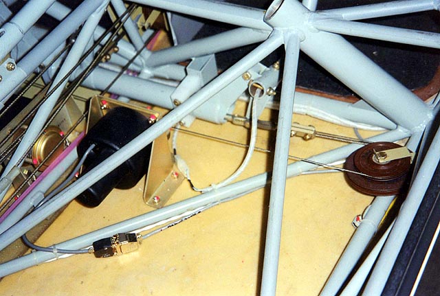
The black box near the pitch computer houses the relays and the resistor. The trim motor connection is done on the wires going to the hat switch.
My own modification
The white box on the photo houses the circuit generating a tone in the headset when triggered by the piezo output of the pitch computer.
The autopilot is connected to the VOR and to the GPS.
I have not connected the directional gyro. (as my existing gyro has no bug!)
The Garmin 195 GPS is installed with a home made bracket on the small panel at the left of the instrument panel. On this panel, I have also installed the Porcine smart coupler control switch ( the smaller one ) and a switch to select VOR/GPS for autopilot reference.( the same switch grounds the wire used on the autopilot to control the gain when in GPS mode.You have to put this wire on pin 42 of the T/C plug as S-TEC does not provide it !)
The Porcine coupler itself is attached with Velcro behind this panel. The whole assembly connects to the aircraft wiring through a 9-pin connector, behind the instrument panel.
In parallel with the Porcine coupler, I have also provided a wire to bring the NMEA output of the Garmin GPS to a socket on the instrument panel, where I connect a portable PC with the Flite Map moving map software.


