Written by John Burnaby
Make a template for the top of the wing in the console area.
Place template on wing in console location and scribe a level line on the template.
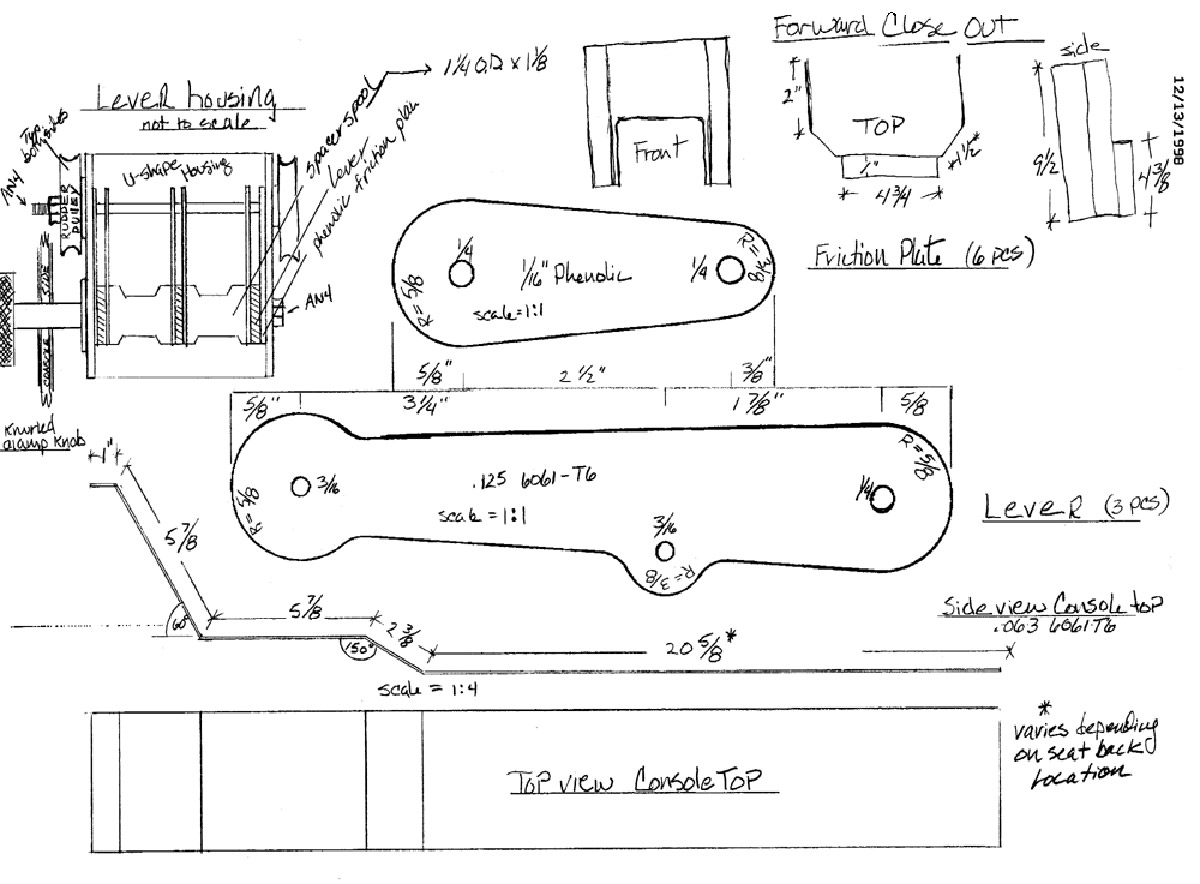
On a flat 2×8, edge glue a block 2x6x6 on the forward end then layout the curvature of the wing from the template. Then layout the side view of the console top from the drawn image, so that the 20″+ dimension is parallel to the level line on the template. Carefully cut out the plug with a bandsaw so that cuts are straight. Brush 2 coats of resin on the plug and let cure. Then wax the sides and top edge with 3 coats of mold wax, buffing between coats.
Note: The height of the forward end of the plug depends on the distance between the wing and the bottom of the panel. Check yours and adjust the template for the plug accordingly
Q-cell 2 pieces of foam for the console sides and then laminate 2 layers per side and let cure. Hot glue the 2 sides together in a couple of spots and trace outline of the plug onto the side blanks. Cut out the console sides with a bandsaw. Clean up the edges with sanding block. Separate the sides using acetone to release the hot glue.
Clamp the two sides to the plug so that the top edge is 1/4″ above the plug and the ends of the sides are matched and square. Layup a two layer laminate in the trough formed by the console sides and the depressed plug. Try to get the laminates tightly in to the corner formed by the plug and the sides. Cut the trough laminates down the center when at green cure, but allow the trough to cure in place. After curing, remove the plug and laminate two more layers on the underside of the trough. These flanges will hold the nut plates that secure the console top.
Quadrant Housing
Make a plug 3″ wide by 6″ long and 2″ high. Make an 8 layer laminate over the plug forming a U shaped part having 2″ legs. Block the part on the inside and drill 1/4″ holes for the Lever and friction plate/rudder pulley bolts. Make sure that the bottom of the part is parallel to the drill bit and the sides are square to the drill bit.
The friction adjusting knob is whatever is in your imagination.
Console attachment
You want to be able to remove the seat pan without having to remove the console. I cut off the inboard edge of the seat pan and bonded angles on the underside of the upper wing skin to hold nut plates that receive 10-32 screws through the side of the seat pan, thus securing the seat pan. Now I can bond angles on top of the wing skin to secure the console without trapping the seat pan underneath it.
There is a part to close out the front of the console that provides a short kick panel and a way to neatly finish the installation. You can see this part in the images that Michael Arbuthnot posted and I have drawn a sketch of it (See Below). This will take another plug to make.
There is one more part that is a cube shape, with two adjacent sides removed. This part is for anchoring the aft end of the control cable housing and is mounted between the lever housing and the forward close out. I haven’t assembled my entire console yet so I can’t elaborate on how this part fits into the scheme of things.


