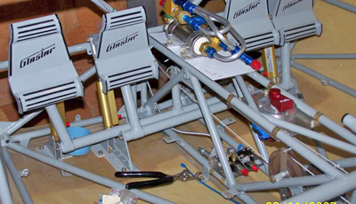
 Installation of the rudder pedal assemblies: The S-H manual instructs you to position one set of pedals, lock it into position, and install the liquid shim beneath the bracket, and after cure, drill the holes through the fuselage bottom. Then, proceed to the other.
I found it better to postpone any drilling until both sets of pedals are positioned on their respective mounting pads, with some freedom to adjust and tweak. It is almost impossible, with the reference points available, to locate the assemblies with the precision necessary to avoid mis-alignment and interferences.
Also, an alternative to the waxing of the brackets to prevent bonding to the shim pads is to use a piece of 2″ wide transparent vinyl packing tape. It’s less messy and works fine. This also applies to the long vertical fin spar mounting.
–Al Sibley
Co-pilot rudder pedals: I chose not to put in dual brake systems, but I did not want the copilot pedals to ever flop over forward and impede rudder travel. Problem: how to spring load the pedals so they would have some feel and also safety feature re above. Solution: use a “spreader” spring (available at the hardware store) with about 2 inch legs. It looks like your thumb and forefinger spread apart with a 2 wrap coil in between. Put one leg down the pedal tube and one leg up against the back of the pedal. Cut a slot in the fwd side of the horizontal tube to accept the coil, and thread the AN3-35 bold through the coil. Bend the tip of the upper “leg” fwd so that it won’t scratch the pedal. Then secure with a safety wire around it through two #40 holes drilled through the pedal. A simple, neat installation.
–Paul Hansen
Rudder pedal installation: In installing the fabricated support brackets for the (horizontal) rudder control bars, they need to be bedded in Q-cell before screwing to fuselage, and of course located both fore and aft, and leveled. Interferences prevent strict parallelism and perpendicularity to the C/L of the fuselage. Rather than attempt to eyeball and adjust individually, I found it most expeditious and accurate to simply spring-clamp the left/right (fore-aft) bars together, insert a 1/16 approx. shim between each bar and the supporting fabricated bracket of the other bar to avoid friction interference, and do the Q-cell embedding. The clamps lock- in the fore-aft location with absolute rigidity; the leveling is easily done with shim blocks.
–Bill Wilson #5278
Rudder Trim: The RV builders have an ingenious-yet-simple device whereby the rudder pedals are attached to springs thru a simple series of cable and pulleys attached to the firewall. An adjustable cogged pulley allows the pilot to adjust bias on the opposing springs and thereby achieve trim from the cockpit. I don’t know if the G/S has similar working room aft of the firewall; I also cannot cite a specific reference with sketches. The one I saw came out of the Ch 393 (Concord, CA) newsletter.
–Bill Wilson #5278
Rudder Pedal Installation: Having completed steps 0.1 to 8 in Section IX of Volume II, I had problems when I later attempted steps 21 and 22 and I think fellow builders can learn from these.
My first problem was that I found the rudder control uprights interferred with the cage structure. Although not specifically measuring the fuselage cag tabs (see Fig 5) myself, I had assessed that they were approximately vertical. Obviously if they aren’t, the clearance or not at the other end will suffer. Builders should check these tabs before doing step 2. I had to bush the control weldment inboard by inserting one of the thicker nylon washers surplus to fitting the cage to the fuselage, on the pivot before inserting the weldment in the tab. HOWEVER, there is a limit to how much thus can be “bushed” – the pivot is not very long! So check the tabs and control for interference before locating the inboard support brackets.
When I came to do step 22, I found the rudder control springs then interfered with the cage. S_H tell me there is a movement of 2 inches forward and aft in the pedals, so this must be clear –full and free movement. I then had to make two steel tabs from my scrap box – left over from the making of the tab for the flap handle (see Figure 84, Sec IX), and in fact bent them similarly to this same tab. Holes were drilled only at each end maintaining like tolerance to Figure 84.The bend was to offset the spring to clear the cage – 1/4″ or so. I made the tabs two lengths – one to approximate the length of the shackle left out (see Figures 46/47), the second that distance PLUS the distance the rearmost weldment is behind the forward-mounted weldment. My idea here was to maintain approximately equal spring lengths.
The tabs were fitted to the rear end of the springs at their forward end, the rear hole being caught by the strap shackle clevis pin in one or other of the two holes provided in the control uprights. These tabs in effect serve two purposes and builders with no interference problems may find it worthwhile to make these tabs (as is rather vaguely suggested in the note on page 93). Firstly to clear the springs of the cage frame as was my initial problem. Secondly, anyone who has replaced a similar spring as is installed on a Cessna (172 at least) as I have will know the act it is nose down trying to achieve this round the pedals, brakes etc.
Fitting them initially on the GlaStar without the firewall is easy, but just think a bit of the situation once the firewall is in etc.There is little room to twist the spring to get it through the appropriate hole, besides stretching them a bit to fit. The tab will thus also allow later replacement of the spring, if ever required, much more simply!
One note of caution. My GlaStar is to be a tail dragger. The area of the rudder springs is also the area where the nose wheel fits, so it may be advisable to check for clearance of this system when offsetting the rudder springs as suggested. Whatever, there must be full and free movement of the rudder control system!
–Peter Washbourn


