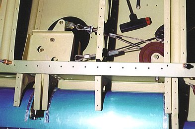
Pulley spacers: Cut spacers (from 3/8″ tubing) to put in between the pulley guards(and over the AN3-17 bolt) on the front pulley group. For small ones, fill with washers. But you need (1) 1/2 inch spacers behind each pulley.. see pages 62, 63 & 66 of the Systems Assembly Manual.
–Paul Hansen
 Small part assembly: When assembling small parts such as washers and spacers in such places as rudder hinges and elevator cables to elevator bell crank, put a small dab of heavy grease on the parts to stick them together (adhesion!) until you can put the bolt or pin through the assembly. You can leave the grease to lubricate the joint, or clean it with a small brush and lacquer thinner if you wish.
–Paul Hansen
Flap Cable anti-chafing strips: Place anti-chafing strips on the flap cables between the seats and anywhere else the cables might rub. Be especially careful of any rubbing on the vertical fuselage tubing. Use plastic Nylaflow conduit and RTV or tie-wrap to structure.
–Jim Londo
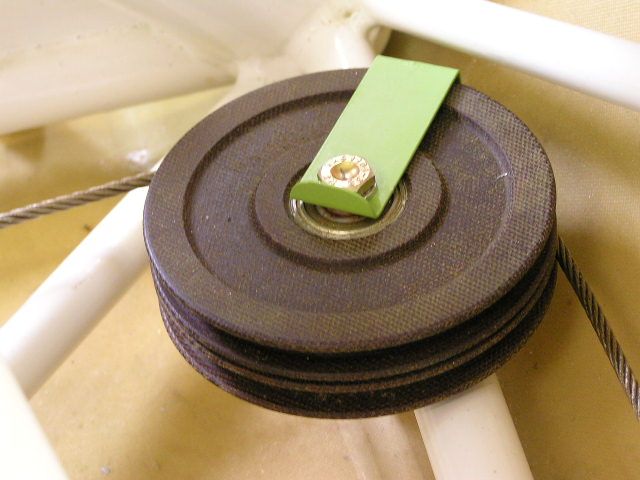
Nico-press: Keep cable Nico-press joints well clear of pulleys.
–Jim Londo
 Cable installation: Color code cables at each joint to keep track of cable ends. Also, there are clips you can get to safety the cable turnbuckles instead of safety wire. This saves a lot of time as you must disassemble and reassemble the cables many times. It also helps to use color string to simulate cable runs prior to installing cables when you position the pulleys in the wings. Don’t rivet the pulley brackets in place until you run the string to check for any conflicts. Use different colors for each cable run.
–Jim Londo
Aileron/flap cables: Fabricate and install your cable retainer straps before you run your cables. Much easier. In fact I recommend that you put them on when you build your wing, and when you first install cable pulleys in your fuselage.
–Paul Hansen
Disoriented control cables: We experienced a problem with disoriented control cables in the left wing after final attachment of the wing. After hanging the wing and attempting to straighten out the cables, we somehow lost one of the aileron cables in the process of having too many people standing around making suggestions.
After getting rid of the people and having back surgery, I grabbed a fiberscope from work and looked into the wing. I found that we had one of the aileron cables routed around (not through) the UHMW guide inboard of the inboard flap track. With the help of the scope, we were able to thread a 1/8″ aluminum tube from the flap actuator opening through the hole in the guide to the wing root. We then crimped a length of safety wire to the tube and pulled it back through the opening. After also pulling the aileron cable back, we attached the cable fitting to the safety wire and carefully pulled it into the correct position. We thought this was a brilliant solution. The fact is we were stupid to allow this to happen.
SOLUTION: On the right wing, before the flap cove was installed, we carefully separated the four cables and placed a piece of duct tape under the cables which were spaced 1/2″ apart in their proper sequence. We then placed another piece of tape on the top, locking the four cables in position about 12″ inboard of the wing root. Now, after everything is closed up we won’t need a piece of space age equipment to see if we screwed up. We will know we didn’t screw up. They probably told us to do this in the manual, but we didn’t read that part.
Spend five minutes to do it right and it will pay off big time. I know!
–Jim Siebel
Trimming control cables: Once the control cables have been routed and adjusted to the proper length, the excess must be trimmed off. The Manual doesn’t really offer an easy way to do this. I found that one of those little 2″ diameter high speed cut-off wheels in an air drill makes the job simple and easy. Make sure to place a sheet of scrap aluminum in back of the cable being cut to protect the rest of the cable.
–Al Sibley
Getting the control yoke neutral: I found the manual a bit confusing on the rigging section. Maybe the following will help: The 18.75″ length of the interconnect rod is a STARTING POINT. From here you adjust the rod to achieve the required system travel. Imagine the rod being super short–the controls would only move a small amount from side to side. Lengthen the rod and the controls will deflect more. This is the adjustment that ultimately will give you your aileron travel setting. Here is what I would recommend to get things started in the right direction:
- Connect up the LH aileron actuation cable ONLY.
- Adjust the cable so that it is tensioned a bit when the aileron is down at 17.5º and the control stick (or bracket) is max. over to the right.
- Now, move the control stick all the way to the left (this will be the up position for the LH aileron.)
- Hold the aileron at max up position with a little tension in the cable and read the travel. If you are more than 22.5º then you have too much travel at the control yoke and you must SHORTEN the interconnect rod. Less than 22.5º and you must lengthen the interconnect rod.
- When all is done at this stage, you should go from 17.5º down at full right to 22.5º up at full left all the while keeping a slight tension on the cable.
- Now, set the control brackets in the neutral position (that is even with each other) and adjust the cable length so that the aileron is neutral also. When doing this step try put a small amount of tension on the cable. Up to this point, you are dealing with one flap and one cable ONLY. Also you are not yet concerned with cable tension yet. The only thing that you wish to accomplish at this stage is to MATCH the yoke travel to the aileron travel.
- Now that we have established (close but not perfect yet) a match between stick deflection and aileron deflection and also have the aileron and stick in agreement with with each other as to the neutral position, connect the RH aileron cable. LEAVE THE CROSSOVER CABLE IN THE BAG FOR NOW!
- Adjust the cable so that the RH aileron is neutral when the stick is neutral. Try to use the same cable tension that you used on the LH side.
- Now connect the crossover cable. Again, try to match the amount of tension that you have been previously using.
You now have a situation where everything is rigged properly but probably nothing is “in sync” with each other. NOT TO WORRY You know that the aileron actuation cables are the right length. Also you know that the ailerons are set for neutral with the stick in the center of its range. What is now throwing things off is a condition of unequal cable tensions.
For instance, as you tension up the crossover cable, you will find that the ailerons will want to droop down. So what you have to do is keep the cable tensions balanced. If you tighten up the crossover cable, you must also tighten up BOTH of the actuator cables.
When all is done make sure that your cable turnbuckles are of an acceptable length.
–Jeff Liot #5141
Locating the control yoke: installing the nuts and washers to mount the control yoke assembly (p. 50) can be a little frustrating. I found a sure fire method. Sick the nut on a resin mixing stick with some hot glue and insert is into the metal box mount. (Sure wish S-H had cut a lightening hole in the center of the box as it would make the job a lot more accessible.)
–Jim Rose
More on locating the control yoke: I cut a strip of aluminum to fit and installed nut plates to match the mount holes. I left the strip long enough so you can hold on to it while you start the bolts. Works great! I cant see doing it with nuts considering the number of times I installed and removed the pivot blocks before I got them shimmed for free movement.
–Dan and Jannell Thompson, 5429
Aileron Rigging: Well in a marathon session last night with all three of us carrying on like puppies in a basket we got the ailerons properly rigged. This is an interesting challenge to say the least. The cables going to the control stick are quite long in relationship to the crossover cable. As a result you have to maintain just about full tension on the whole system while you are rigging. The book needs a little help here. It starts you out with the carry through tube that connects the left stick with the right stick being way too long. Control cable tension is something I have not been able to find in the manual so I used 25 to 35 lb as the range to work in. This is common for 1/8″ control cable. If you will recall when we looked at that airplane in Sebring he had his cable rigged to 60 lb, and they felt WAY too tight. I welded up the struts that are used to fold the wings and have them installed. I think before we remove the wings to install gas tanks and such we should fit the top hatch and windshield. As Mike suggested we can then fiberglass down rather than working overhead.
–Tom Lempicke
Aileron cable installation: Just finished the control cable campaign for the ailerons; here is what worked for me. Before attempting to adjust, and to keep cables manageable, in place, and identifiable, I first:
- set the various guides, including the overhead “comb” in the cabin
- set the cable guards in order to keep each one in its pulley groove
- color coded each cable along its length.
To exert an approximately equal tension on each cable, I adapted an extra hand-drill chuck with a 3/8″-24 eyebolt threaded into the motor end (cut off a 3/8 bolt, heated and hammered and drilled the eye), into which I chucked the cable end, and pulled tension with a length of rubber tubing threaded thru the eye and stretched to the max and clamped off anywhere convenient. All this because I work alone. I basically followed the manual for travel adjustment, i.e. adjusted the interconnect rod to stop at the proper 17.5° down travel. Unfortunately, the interconnect rod was too long at its shortest, so I welded a threaded 4130 bushing into the pivot, which allowed an adjustable stop bolt and lock nut. With the down travel on each side thus set, I was able to tweak the up travel to 22.5° degrees by small adjustments on the threaded pushrods. When all was said and done, the degree travel was right -on for both sides, tho the bellcranks and interconnect rod were not precisely at their measured neutral positions…but no one will know but you and I.
–Bill Wilson, #5278
More on aileron cables: Like Bill, I found the interconnect rod was too long, but unlike Bill, my stops are temporary packers held in place with double sided cellotape (as per the suggestion in the manual, or maybe through the forums-somewhere). Will be having a closer look at your idea of adjustable bushes when I have the fuse back in the workshop. Not sure that I fully understand your idea, but like the adjustable bit of it! Am concentrating on internal fitting of the wings at present.
The second “problem” I had was whilst I could get plenty of up travel, I was scratching to get the full down travel, finally just scraping in. I found the aileron push rods touching the cutout edge in the spar – had to get in with a bastard file and take some metal out. If I was making the inboard aileron hinge assembly again, I would put the manufactured head of the rivets holding the attach angle to the hinge arm on the cutout side of the assembly. I have the shop head on that side and some of the rivets are close to interfering after the filing of the spar has been done. Not so easy to get in again now with the assembly permanently in place, to knock the rivets a bit tighter to provide better clearance. I’m happy, but suggest others may care to watch closely and make sure the appropriate rivets are driven if the shop head is on the cutout side, maybe the critical ones even overdriven a bit, to ensure clearance. My pushrods are pretty much half way in the cutout at full down, so the rivets in that area are the ones to watch. (Note: I think I made my cutout 3/16″ lower as per a builders note. I see I have a note in my manual of this and I’m pretty sure I followed it. If I did, it’s pretty right because my pushrod is central as built)
Update to the above: Further to my “problems” outlined above, I have further investigated the interference in the control rod slot. In re-swinging the flap and aileron in preparation for fitting the wing tips, I have re-spaced the bushes on the bolts on which the ailerons pivot, giving me better clearance and also I believe greater travel. I was able to check tolerances between flap and aileron and aileron and wingtip and wingtip and counterweight and get the best for each.
Suffice to say that the bushes supplied for the aileron pivot bolts are “generous” and require cutting down as indicated in the instructions. If you haven’t enough travel like me, take a bit more off. But don’t be too heavy handed, and cut square with the hacksaw! The more you take off, the greater the gap between the flap and aileron. Mine is now about 1/4 inch.
Other than that, the step went pretty much as Jeff described it, other than it is winter here and I didn’t partake of the beer for the job well done – coffee instead.
–Kiwi Pete
Installing the control yoke assembly (Step 10 – Systems: page 51) calls for sawing the ‘UHMW polyethylene control yoke bearing blocks’ in half and then inserting washers to compensate for material lost in the saw kerf. Beware! Metal washers tend to damage the Control Yoke Assembly. Instead we sawed a large nylon washer (provided with kit and approximately 1″ diameter, p/n 085-0004-01) in half producing two U shaped sections which fitted the gap better and safer.
–Frank Miskelly #5577


In order to comply with Service Bulletin 48 Part 2 is it necessary to cut additional access holes in the wings to access the Upper Inboard Aileron Guide Pulleys?
Also, Is it possible to remove the bolt for the aileron guide pulley in the cove skin without damaging the bracket?