Fitting fuel tanks: When fitting the fuel tanks into the wings, the spar spacing at the upper wing surface tends to spread apart when the upper skin is removed. I found it helpful to cleco the upper inboard 5 skin stiffeners into place to preserve the proper spar spacing. The tank clearance needs to be checked with these in place anyway, so both requirements are met. I also found that in my wing, the 1/4″ thick neoprene was too thick to fit between the spars, and I had to use 1/8″ neoprene baffle material on the forward and aft surfaces of the tanks.
–Al Sibley
Tank bumper material: I went to my local complete hardware store and bought 1/8″ Neoprene rubber in 12×12 sheets. I then used two layers of the material most places. By using eighth inch material it bends around the tank better, and I used a contact cement to glue two layers together. Though in some places there was only room for 1 layer.
–Paul Hansen 5003, N43PH
Tank bumper material: I went to a local shoe repair shop and bought a 4×12 piece of Neoprene (used in making replacement heels) to use for tank bumper material.
–Glenn Culver
Tank bumper fitting: I noticed that some of you are getting ready to slide in your tanks. Well now, I can’t say how well the procedure in the manual works as I scrapped it. It seemed to me that if I glued a bunch of rubber to the tank, I would have mega trouble sliding the puppy in over all of them rivet ends and other protrusions that are hanging off the inside of the spars. So what I did was get hold of some 1/4″ neoprene rubber and cut out some fancy shapes and glue them on to the inside of my SPARS and my end RIB. My tank fits snug as a glove and I can slide it in and out with ease. Just a thought-the smooth tank slides over rubber better than rubber slides over hills, valleys and rivet protrusions!
–Jeff Liot 5141
Thread sealant: Someone asked me (and I accidentally erased the e-mail) what RV builders used to seal threads. I am told that Permatex thread sealant with teflon (Permatex #14A) is used by many for this purpose. I bought a tube to try it out. Don’t know what was used on my RV-3A, but I have no fuel line leakage and haven’t had any. Can’t say the same for plastic brake lines. Replaced them with aluminum lines last year. The plastic ones lasted about 8 years but when they went, leaks erupted everywhere almost overnight. With aluminum lines, my brakes work much better. And I think they’ll be more reliable.
–Joe Colquitt, GlaStar 5218
Fuel valve modification: Unfortunately I don’t think using oversize fuel vent tubing is going to cure the problem of uneven tank fuel usage.
The two vents are not interconnected and so you are always going to have a small differential pressure from the right tank to the left. As a flight instructor I got to take many cross country flights in Cessna products and had the gauges right in front of my nose. One tank will always empty before the other, and it can be hard to sit there and watch it even when you KNOW that sooner or later the two tanks will even out.
Bill Jones came up with a nifty solution that we are adopting. We bought a fuel valve from Aircraft Spruce that had a left – right – off position setup on it. The core of the valve has an “L” shaped hole through it. We then took it to a machine shop and had the hole bored out so that it is now a “T” shaped hole. We now have left, right, both, and off positions. By taking the 90 degree ell fittings that go into this valve and threading them just a little deeper than the factory does it fits nicely into the space provided in the GlaStar.
After Bill started flying his airplane we asked him how it was working out and he said “Just fine”. The additional goodie you get out of this is an “off” position. Much more important than you might think. This airplane will transfer a whole bunch of fuel in a short time if the ramp is not level and with the standard setup nothing can be done about it. With the selector in “Off” that can not happen.
The fuel valve is sold by Wicks Aircraft. It is called an Allen Fuel Valve. Part number 6S122 – price $123.67. the handle for it is part number 38485 for $2.41 and the set screw is part number 38532 for $0.32. I believe that a letter “H” drill is the correct size for drilling out the passage. As received it will have an “L” shaped passage. After drilling it will have a “T” shaped passage. We had the proper setup stuff and a vertical mill to use to do the drilling. If you don’t have the right equipment you should consider taking it to a local machine shop. After you drill the spool of the valve the handle will no longer point the right way. You will have 4 positions – off – left – right – both. We are planning on grinding a new flat on the stem of the valve so that the handle will point correctly.
–Tom Lempicke
Comments on Tom Lempicke’s tip above: Tom’s remarks about the modified three position to four position fuel selector are “right on” with one exception. In the “off” position fuel is denied to the engine but the left and right tank may still cross-feed if the airplane is on a slope. The “T” configuration of the fuel passages in the “OFF” position align the top of the T with the left and right tank fuel lines, the bottom of the T faces aft and there is no passage facing forward thus no fuel can be directed to the engine. If cross-feeding cannot be avoided otherwise you can select either tank and the fuel valve will then prevent cross-feed but will not be “OFF”. In spite of this shortcoming I am very happy with my four- way fuel valve as it allows excellent fuel management in flight to accommodate uneven fuel flow (which has not been a significant problem) and fuel transfer from aux to mains. So far I have avoided having fuel drain out of the vents in copious amounts on the ground by only topping-off just prior to flight and trying to park on relatively flat ground. In 52.7 hours of flight I estimate a loss of fuel to be about 2-3 quarts and that was because I did not pay attention to the slope. Also, N186GP is a tail dragger and I expect that exacerbates the cross-feed out of the vents problem when tanks are full and is a bit of an advantage when they are down a bit. Hope this helps.
Bill Jones, #5186/N186GP
Fuel caps for aux tanks: I had read that there had been a problem of people loosing fuel from the aux tanks vents. I am not sure how the S-H aux tank kit is made, but if you fabricate your own tanks and use a filler neck similar to the neck that comes with the main tanks (I used flush fuel caps for the main tanks so that I had the filler necks supplied with the kit left over to use with the aux tanks), you can run your fuel vent up into the neck of the fuel filler neck. Here’s what I did:
- I Bought a brass compression fitting suitable for 1/4″ OD tubing with the proper size male threads to screw into the vent fitting on the outside end of the fuel tank. I had placed the vent fitting for the aux tank in the same place as the vent fitting for the main tanks.
- Drilled out the inside of the brass fitting with a 1/4″ drill. And then screwed the fitting into the end of the aux tank.
- Ran 1/4″ tubing through the fitting and into the inside of the aux tank, bending the tubing so it goes up into the filler neck with the end of the tubing just below the bottom of the fuel cap. I fastened the end of the tubing to the side of the filler neck so that it would not be hit by the fuel nozzle when fueling.
- Ran the other end of the tubing down through the bottom of the wing at the wingtip as shown in the S-H instructions.
- Tightened the compression nut on the fitting to seal the tubing where it passes through the fitting. Now, fuel will have to get up into the top of the filler neck in order to be vented overboard. Much less fuel should be spilled than if the vent ran directly out the vent fitting on the end of the tank. I replaced the S-H fuel caps with a better-looking chrome cap.
I also put a tie-down ring on the bottom of the fuselage underneath the horiz stab. I attached the ring to a bracket attached to bulkhead D. Since I am building a tri-gear, I used a bracket similar to that shown for the tailwheel (see S-H instructions on making tailwheel bracket)
–Richard Yerian, Phoenix, AZ GlaStar 5228
Fuel line installation: While reviewing the fuel system lines at the upper wing attach area, I thought of another way of connecting the system: If you can not find a beading tool for the top of the fuel lines, you could flare the end (37 1/2 degree) and install an AN818-3D Nut, AN819-3D sleeve to a AN840-6D Hose Nipple? Hose nipples also come in 45 and 90 degree configurations. A little more cost & weight though. Now that I think about it, think I will get a hold of a beading tool. Nice simple way of getting the job done.
–Jim Rose
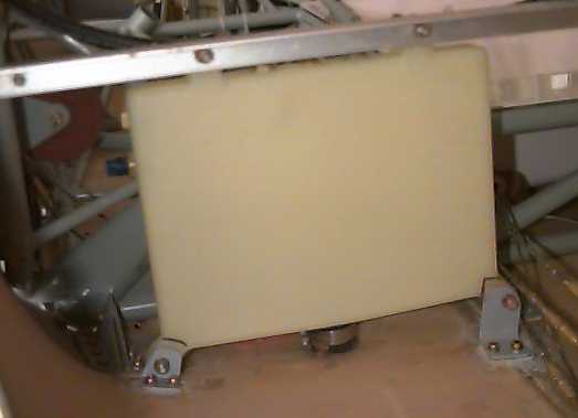
Plastic fuel header tank: Well after lots of thought, I decided to add a 1 gal. header tank to the Star. I did not want to go with the two lines and four way valve modification nor did I want to leave it as designed. And, S-H may also come out with one (Injected engines could use it). What I did was install a KitFox tank. It sells for $100 and has all the brass fittings installed and four attach flanges for mounting. At the top, there are three bosses for right-left tank and vent. On the right side, it has two outlet bosses for a Low fuel level indicator and a gas return line. At the very bottom (facing down), is a boss for draining (water check etc.) and about an inch above (and facing forward) is a boss for fuel delivery to the plane. The drain goes through an alum. flange (1.25 air vent flange) to the planes outside surface. I nice way to make the interface (just one hole with the flange epoxy’ed to the outside).
I choose to use rubber hose in lieu of the alum. lines. Easy way to route them. Also a small ball valve on each tank line, but that is off the header tank subject.
–Jim Rose
Fuel valve: For those who are using the S-H issue Nupro (Swagelok division) fuel valve, and want to have a true panel mount with bracket support, there is available from the factory a panel mount conversion kit. the part number is B-5PMK-P4T-RD for red, BK for Black, etc Included is the bracket, snap ring, replacement plug with extended stem length, and handle of your color choice of several. Cost is $12.90. I purchased through a Swagelok distributor in Concord, CA called Oakland Valve and Fitting (925-676-4100) via credit card, though I’m sure there are other distributors across the country. Since I’m using two valves in parallel, I converted the one from the kit, and purchased a second in the panel-mount configuration at $44.50. Part number is B-6P4T-PM-Color Code. Both units come with installation instructions including hole template and dim’s. The two, one for left and one for right, will give me L-R-Both-Off.
–Bill Wilson, #5278
Fuel line beading tool: Here’s how to make a tool to put the ridge on the fuel line where the rubber hose is clamped.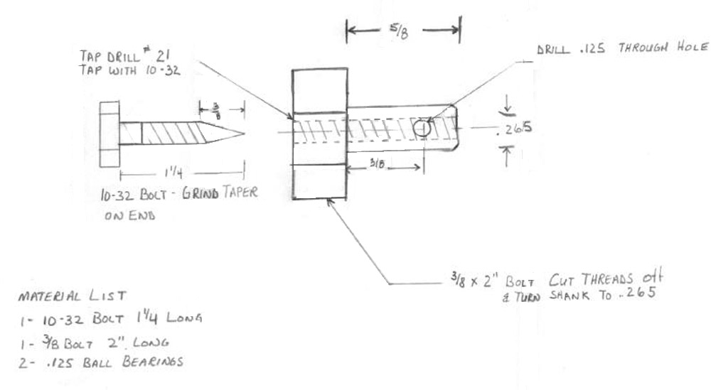
Take a 3/8″ bolt 2″ long or shorter and cut the shank down to 5/8″ long. Drill down the center of the bolt with a #21 drill (265 +/- .010) and tap to 10-32. Drill a .125″ hole all the way through 3/8″ from the head of the bolt. This hole will accept two .125″ stainless steel balls that can be purchased at local bearing shop.
Take a 10-32 bolt 1.25″ long and grind a point on it tapering back 3/8″ from the tip.
To use, put a little grease on the cut down bolt to hold the balls in holes and insert into fuel line. The 10-32 bolt with the taper on the end forces the balls out as you turn the cut down 3/8″ bolt with a 1/2″ wrench.
–Jim Coonan
Mounting Facet fuel pump: When mounting the Facet fuel pump, I installed two (floating) nut-plates on the bottom flange. This will make the installation and especially any replacement of the pump a lot easier.
Flowmwter: For $367, one could install a flowmeter downstream of each Aux. tank and one duel flow meter gauge that will show you exactly how much you have pumped out of each Aux. Tank. Currently, I have installed just the single unit down stream of the header tank. I like to know the flow rate/Hr. and total used. $308.00 These flow systems are FloScan from West Marine Catalog.
–Jim Rose
Fuel line beading tool available: Fellow builders, I finally finished fabricating a beading tool that is based on a tubing cutter. This will form a bead on the supplied 3/8 line that duplicates the bead on Piper aircraft (my sample was from a PA-20). This is available to loan to any builder who will pay postage from Alaska.
–John Stoner, 5290
Making flush caps flush: I have installed the flush fuel caps from Danny at Airlink and encountered a problem with the aux tanks. I haven’t seen it discussed here so I thought I would bring it up. The main tanks were ok after I beat them into submission to get the warps out of the top of the tank so the cap would fit flush with the skin but the aux tanks were another matter. With the cap screwed all the way into the tank, the cap was still 5/16″ above the skin (not very flush for sure) so I built a wood jig to hold the cap flange 1/8″ below the hat section. I then heated the aux with my heat gun 6 to 8 inches around the filler neck (hot enough that I couldn’t hold my hand on the tank). I then let it cool down for about an hour (lunch time) and when I removed the wood jig the flange stayed in the new position. I now have 4 FLUSH fuel caps that are of top quality as is everything I have purchased from AirLink.
–Charlie Walker #5603
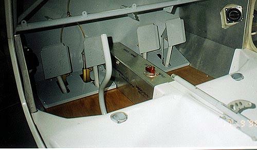
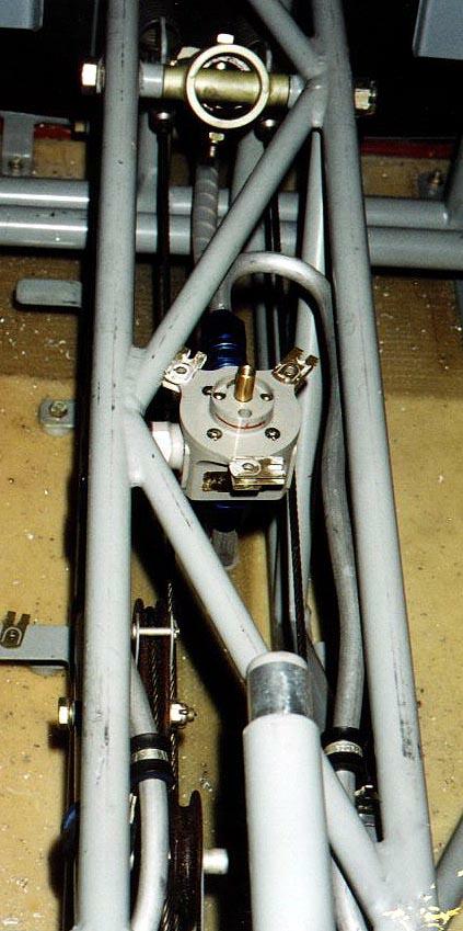 Fitting an Andair fuel valve: We have an Andair fuel valve fitted in our GlaStar. The model is FS20X4F, (left, right, both, off). The valve has two female inlet fittings being for the left and right fuel inlets, and a male outlet to the engine.
The valve is situated in the same space as the Stoddard-Hamilton on/off valve shown in the manual. The left fuel line runs to an AN822 flared elbow (with appropriate sleeve and back nut etc, etc) which screws into the left inlet on the valve. The right fuel line continues a little further forward and is pulled into a 180-degree turn and screws in the AN816 nipple on the right female fuel inlet of the valve.
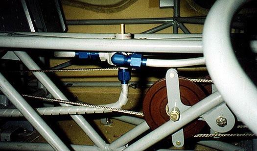
 The fuel outlet line to the engine is connected by an AN6 flared fitting. This line is also 3/8″ and continues forward with a slight bend to the right around the nose wheel position and finally through the fire wall at the same level and slightly to the right of centre. The fuel line is protected with spiral wrap to reduce the chance of chafing. Immediately on the engine side of the firewall, we have installed an Andair Gascolator.
The fuel valve is mounted on its own aluminum support, which sits across the central frame. A centre aluminum panel will be installed around the valve, with the corners bent to fit. This allows for the non-removal of the valve each time the covers need to be removed for regular ‘check and maintenance procedures. Both the left and right hand sides of the covering are slightly away from the sides that allow room for the bolt head and nut, which holds the nose gear in place. This space allows room for the elbow flared fitting needed for the left fuel inlet.
–Daryl and Jane Grove #5154
Check valve: In 98PW I have the standard SHI tanks with a check valve at each incoming air vent. This check valve is available from Aircraft Spruce. It allows air to freely pass into the tank and has a pinhole to allow fuel or air to escape if pressure builds up in the tank. I also have adjustable air vents which allow each tank to pressurize equally in flight. With this setup, my tanks burn down evenly and I usually refuel when I have about 4 gallons per side left. At 65% power, burning about 7.2 gal. per hour, I have nearly three hours of flight time which is long enough even in this great airplane. Also with the check valves, I lose little if any fuel when parked on a slant and none with any unusual flight attitudes.
–Richard Wass
Pressure-testing fuel and oil lines: In fabricating and pressure testing fuel and oil systems components, a safety margin for proof and burst must be considered. I make aerospace fuel and oil components where I work. The standard we typically use for our turbine engine systems is proof pressure test at 2.5 times the maximum operating pressure and burst testing at 3.5 the maximum operating pressure. Other systems will vary depending on the flight safety factor of the component.
Proof testing, if the product is designed correctly, will be below the elastic limit of the materials it is made from.
Burst testing will be below the ultimate limit of the materials it is made from. Parts that are burst tested should not leak but are no longer usable for flight components even though they may look fine since if designed properly, the materials will have used up their fatigue life by being stretched beyond the elastic limit.
Burst testing is usually done only as a part of original part qualification, but proof testing is performed both as part of fabricated product acceptance and as part of maintenance inspections. You will see proof testing done on SCUBA tanks, high pressure weld gas bottles and now propane tanks for your BBQ. It is a safety issue.
Typically, our GlaStar uses fuel and lube components that will handle pressures many times over their operating pressures. Fabricated lines especially flex lines should be pressure tested with air since the connection between the hose components can leak if done incorrectly. Testing with air under water is better than using the actual fluid since it is easier to detect, doesn’t leave a residue and the air molecule will pass through a hole many times smaller that the working fluid.
Aluminum and stainless flared fittings lines can leak but are difficult to impossible to test as a system at anything other than operating pressures.
This is where close visual inspection during fabrication is so important. In this case, careful inspection for cracks in the tubing, especially at the flare should be done. Check the sealing surfaces of metal lines and fittings with a 10 power magnifier looking for tooling/handling marks that may cause the joint to leak.
Protect all exposed sealing surfaces when the component isn’t assembled from damage by using a plastic cap or tape.
All metal lines should be well supported in aircraft structures to minimize vibration of the line or induced vibration from adjacent structure that may cause fatigue and leaks. Care should be taken here to support the line, not lock it down. Aircraft fuel and oil lines are usually supported by rubber lined clamps that allow the line to move a little. All lines should not touch structure if possible. All metal lines should be connected without being restrained in position. Typically, a good flared tube connection should be able to be located on the flare by itself before the nut is screwed on. Never install a straight length of metal line between two rigid fittings.
Look at AC43.13-1B, Para. 8-31 if you have it.
–Gus Gustavson, 5581
Slosh-clean your fuel tanks: When I put in my main tanks I decided to slosh some gas around in there before final installation and found, on running the gas through my blue shop paper towels that there were huge amounts of tiny metal particles in the tanks. After the welding and all the banging around on the tanks it loosens some particles that could potentially clog things up down stream. (Slosh-clean means pour in a some gas; pick the tank up and shake it around, including upside down; then pour out through a filter and check the filter)
I received my new header tanks this week and this morning decided to just check and slosh clean them. Sure enough there were a few particles on the filter paper. Safety first! I don’t think this says anything about SHAI and their sub-contractors or who ever makes the tanks, but you can’t be too careful. It’s our bodies up there in these things! Incidentally, we are having incredible, CAVU smooth air fall weather here in Colorado. Hard to get the old girl to head back to the airport this morning.
–Paul Hansen 5003, N43PH


