Gear parts: In doing the gear, I am finding a lot of parts missing: nut plates, several different bolts. Read through the manual to see what is called for, and then check your inventories to see if you have them. Many discrepancies between the box lid inventory and the main inventory. Parts boxes were filled from the lid inventory without checking the main inventory. Also Gear manual calls for some bolts that are on no inventory. Check it out in advance so you can call them and get what you need before beginning! Other than that it is going fairly smoothly. Drilling the holes through the gear legs is real tough! I did my axle holes on the drill press. But socket holes have to be done in-situ!
–Paul Hansen
Brake pedal travel: To facilitate better rudder pedal travel and brake piston actuation: The upper left edge of the brake actuator bracket (the 3 1/16″ dimension) needs to be brought straight down almost to the beginning of the radius to the left. See page 32 of Systems Manual, Figure 10.
–Paul Hansen
Toe-out: I have my gear slightly toed out, about 1/4″ at 36″ forward. It works fine there.
–Jim Londo
Gear leg drilling with a drill press: Hold off on the “anti-seize” until you install the gear. It makes your wife’s hands all grimey.
- Line up the gear per SH directions. I used a scissors jack under each end of the angle stock for easy adjustment.
- Mark the location of the hole on the gear socket (front).
- Drill at the mark with a 1/8″ bit. Drill through the socket deep enough to make an indentation in each gear leg.
- Remove the gear legs and use your drill press, running at slow RPM, with a vee block and the gear propped level to drill 1/8″ hole at the indentation mark on each leg.
- Drill the front hole on the gear socket larger – say 1/4″.
- Reinsert, relevel and adjust toe-in or toe out with a 1/8″ bit in the gear and socket hole. The oversize hole will allow for adjustment.
- Drill with the 1/8″ bit through the back side of the gear socket.
- Remove the gear legs and use your drill press to step drill the hole in each gear to 5/16″ final size.
- Step drill up the back side hole up to final size.
- Repeat step 6.
- Drill from back side hole through gear to drill front socket hole to 5/16″
You should end up with centrally located holes and perfectly aligned gear. I used regular bits running at low RPM without any problems. I drilled holes and alignment for both a tail dragon and nose dragger in about 2 hours and no broken bits.
–Roy Kokenge
Brake line installation: When installing the brake lines, I put a nice easy loop at the bottom so as not to stress the line. There seemed to be plenty of clearance between the line and the brake disk. (1 inch). But in doing taxi tests, when I burned in the brakes, the pressure on the line of holding the brakes on pushed the line over against the hot brake disk and melted a small hole in the line!! (so I had to order new line and compression fittings) (I’ve gone around in circles many times metaphorically in building this plane, but this time it was for real!) This resulted in losing the brakes on one side and I found that the rudder alone will not straighten out the nose wheel when it is full deflection swivel to one side. So I had to shut down and push the plane back to the hangar. With the new pant backing plates (which I am installing this may not be as much of a risk. But I wanted to pass on this word from one who has been there! Make that loop a little tighter.
–Paul Hansen
Gear leg reinforcements: There are three ways used by RVers. (1) Tape a hardwood stiffener to the gear leg and cover both with the sheetmetal fairing; (2) fiberglass the hardwood stiffener and gear leg together into one mass with a sheetmetal fairing covering the mass; (3) do (2) but cover the mass with a fiberglass cover. There are several RVers who sell fiberglass fairings for RV gear legs. RVers who buy this alternative simply substitute the aftermarket fiberglass gear fairings for the RV kit’s metal fairings.
My hangar partner with an RV-4 has had (a) bare gear leg with metal fairing (kit style), (b) # (1) above, and (c) now has # 3 above. He likes # (3). I have none of the above. My RV-3 still has the bare gear legs (no wood or fiberglass) with metal fairings. I also have a gear shake at certain speeds, but I quickly go through those speeds on takeoff and landing so I have no problem there. Where I do have a problem from time to time is on a long taxi. I can get a shimmy that can be eliminated only by stopping before going on. That is a true problem only when the tower is telling me to keep up my taxi speed because of the 747 on my tail. 😉
–Joseph A. (Joe) Colquitt
Brake pedal placement:
- The uprights interfered with the cage on either side. Got over this by using a nylon washer (the thicker) from the cage attach supply to bush the weldment on the outboard ends.
- When I fitted the rudder springs, they then interferred with the cage – move your pedals towards the 2 inch forward limit and check! Got over this by fitting a z tab, like the one under the flap handle, but without the centre hole. Fitted the forward end between the cable strap, utilizing only one of the holes therefore in the upright. The other end took the spring which was then fitted to the forward tab. The bend cleared the spring of it’s interference.
- I could also not meet ALL the measurements for positioning the lower brackets for the brake cylinders. After discussion with S_H dropped one of the requirements and achieved the best fit I could. Think the one dropped was the distance below the centre line of the weldment. But now you mention it, didn’t check the full forward movement of the pedal for it hitting the front weldment pivot – did knock paint off in my first plays! Now have 25 deg rudder travel, but haven’t nicropressed the fittings and thus checked movement with the cable at the correct tension.
–Kiwi Pete
Master Brake Cylinder Installation: Well I just finished installing the pilot and copilot master cylinders. I started these last September when I was working on the fuselage. I took a small break and built the rudder, elevator, horizontal stabilizer and the two wings. For some reason I would walk up to them, tinker and then walk away again. each bracket on the floor of the fuselage was installed differently. The evolved technique was to build up the required support under the brackets using thick fiber glass mat tape. Floating the brackets in a goop of micro was a mess and did not add any strength to the supporting structures. I also did not like using countersunk screws in the bottom glass and foam sandwich. I ended up using large stainless steel countersunk washers to reinforce. Pilots have been known to rip rudder pedal mounts out of inadequate fiberglass floors in a panic stop.
Someone recently mentioned the inaccessibility of those cotter pins in the bottom of the master cylinders. At some point you WILL have to remove them to service the cylinders. This will occur after you have installed the firewall. Instead of cotter pins I used hair pin clips. I went over to Sears and to my surprise found .054 x 7/8 hair pin clips Stock # 533-D These can be tightened a little with a vice grip, and installed in place of cotter pins. This is not aircraft approved methodology. It is simply what I did and approved by me under the EXPERIMENTAL umbrella. You may have to defend this to the inspector, but if he gets far enough into the aircraft to notice them, he will have to ask for your help to get out. This is where you ask if he approves of the clips. He will probably see your point.
–John Steichen 5467
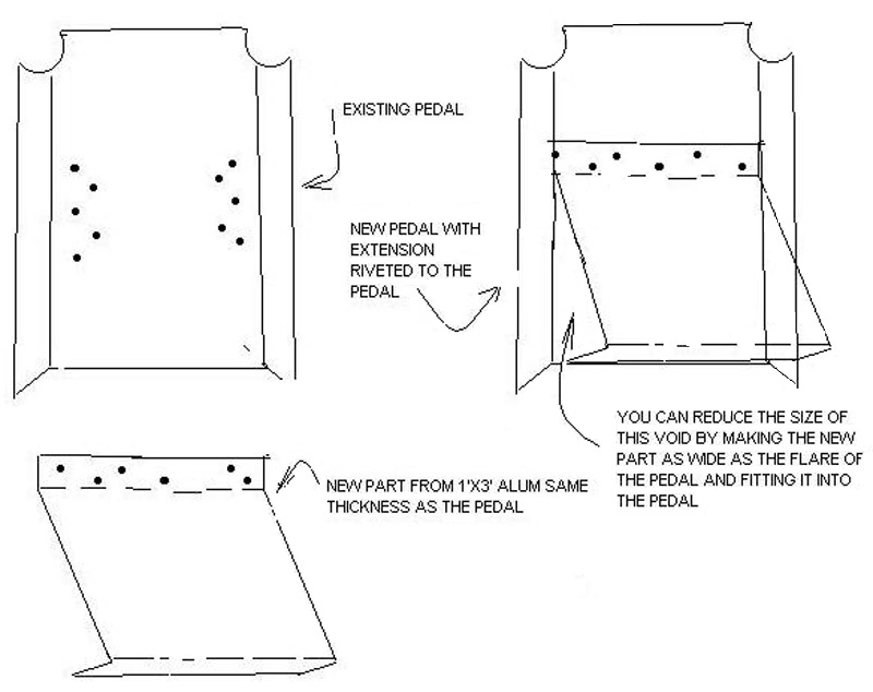
Brake pedal travel: At Arlington several GlaStar builders indicated the “home made” pedals caused a problem on taxi with brake dragging. The pedals require the ankle to be flexed beyond 90 degrees to avoid brake application.
If you have heel cord shortening, a common non-fatal malady, except on landing with the brakes applied, you will have a problem with brake dragging.
The fix is to add an extender at the bottom of the pedal. I didn’t like some of the fixes and here is my fix that looks like it was supposed to be that-a -way.
–Roy Kokenge
Brake master cylinder reinforcement: This one comes from Myron Aadland. Take 12″ long by 5/8″ wide strips of .063 thick alum. and put a 1/2 (90°) twist in each piece (one per master cylinder) Myron used Adel clamps to secure the upper end to the lower horizontal tube on the firewall, but I improved on that idea and bent the upper end into an Adel clamp shape to fit the tube. It saves hardware ,weight, and time! The lower end is bolted to the side of the master cylinder mounting brackets. If you want to do it up right, make some small 1/2″ long bushings from the 5/16″ dia. door latch tube and install these on the AN3 bolt between the brackets.
–Ted Setzer
Locating master brake cylinders: Had a lot of fun doing this and here’s a few suggestions:
Neutralising the pedals is the easy bit. I jammed an appropriate length of stick between each of two pedals and the firewall cage frame and taped them there, then taped the pedals themselves vertical. (Plan to use the sticks later when neutralising the rudder is required) I had trouble getting the 7-7/8 out of my cylinders. Got 8 and no less. Came to the conclusion there must be different types of cyclinders used from time to time – mine were Matco, and I had to be happy with 8 inches.
The next measurement was forward from the tube (working from memory, so no exact details). I measured the diameter of the tubes and the gap between them, then deducted the appropriate measurements (1/2 a tube+the gap+ front tube dia.) then measured from the forward edge of the front tube. Taped up a Mickey Mouse support between the cylinder and the pedal tube (I think) and wedged this upward till I had the correct measurement (probably nearest 1/16″ rather than 1/32″, if that was what was called for. – I agree, it’s pretty hard to get at right angles to take measurements) I had a set of calipers (I think you call them – can set and lock in measurements, but a bit of U bent wire set the correct distance would do the same, and these made it easier.
The last measurement is the worst. My first pedal came out exactly right with no fiddling. The second was miles out and I can’t see what you can do if all the previous conditions are met. Seems to me that it might be mathematically impossible, but I don’t know how to prove it. Any way, I reckon provided the pivot for the bracket is no higher that the measurement set out you’re OK. i.e. the bracket should be lower rather than higher. Talked to S-H at the time and whilst I can’t remember the reasons, that is what I recall as being the solution.
When it comes to fitting the brackets, I shaved a bit of wood the right thickness and roughly the same shape and taped it between the pair of brackets. I didn’t seem to have enough hands otherwise. The wood also stopped the q cell mixture pushing up too high between the brackets, although this can be filed off afterwards. The other concern I had was that the brackets were far wider (as specified in the manual) than the bottom of the cylinder, and I recall I was concerned they would interfere with the base rather than pivot on the bolt. Hence my thought earlier that perhaps some other cylinder had been used at times. Anyway, I added a washer to the bottom bolt when I finally fitted them to ensure they didn’t catch on the bracket Nothing too specific to work on but stick at it.
–Kiwi Pete
Locating the brake master cylinder bracket hole locations:
- Make fixtures from scrap 1 x 2 pine orjust about any stock mat’l
- Mark layout lines to establish 7/8″ hole and it’s related dimensions.
- Drill hole with 7/8″ spade drill or equiv
- Drill a small #50 hole at the 2 1/2 by 3/8 (or 2 – 13/32″ x 1 1/4″) location.
- Band saw fixture to sketch. Check fit to assure clearance on forward tube (not necessary for the forward tube location).
- For the front tube, I hot glued a resin stick to the end to establish and hold the fixture level to the water line. The right fixture can be cut so that the forward tube will support the fixture in the level position. Or again, add a support stick to hold it parallel to the water line.
- Insert a small nail into the #50 (or any size you want to use) hole. This index pin will then establish the proper location for the bracket hole.
- Plane must be in flight level position or level will not establish the true vertical position.
Template: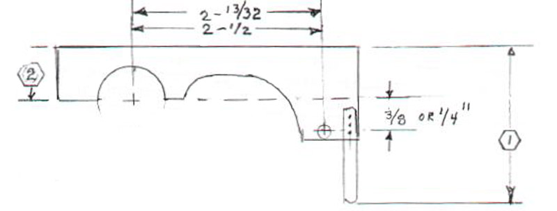
- Dim length to hold top of fixture level and parallel to water line.
- Make sure that the top of the fixture is parallel to the center line of the 7/8″ hole axis.
–Jim Rose
Gear alignment: My gear had approximately 1/2″ differential, i.e. one leg flush with the socket, and the other about 1/2″ below. In checking with Cal S., I learned that the main criterion is to keep the hole within the 3/4″ “land area” within the socket, and within the open bored area of the leg, yet not “too close” to the edge of the bore. Luckily I was able to achieve level and meet this condition. My main concern was toe-in, as several have reported tire wear using the .063″ shim. I used 0.040″ shim, which may be academic in any event. The fit was so tight of the leg in the socket that I believe the leveling 2″ x 1/4″ steel angle tilted back under the clamp pressure, rather than the leg turning in.
–Bill Wilson, #5278
Nosewheel installation: Just finished the nosewheel section, and while this may not be news to prior builders, I did everything off of the airframe… on the bench with vise and clamps, etc, and it went smoothly and accurately. The part about adjusting the axle nut tightness against the washer springs with a fish-scale tensiometer has apparently been informally superseded by S-H. I found the fork had just enough warp that the fit of the bushings on the axle was super-stiff… the notion of 10-15 lb pivot force was moot. Bruce B. at S-H suggested this will wear in, but meanwhile, they have changed their adjustment technique to be “turn the axle nut 11 flats, or 1 and 5/6 turns” after making contact with the washer springs. This I did, and it is indeed very stiff, and I hope will loosen with use. Bruce’s other suggestion was to drill 2 cotter key holes at 90 degrees to allow future adjustment of 1/2 flat turns.
–Bill Wilson, #5278
Matco brake problems: An observation of interest from Airlink. We have installed quite a few brake systems in the Glastar and have observed a problem with the Matco brake cylinders. The machining finish on the plunger shaft seems to be less than desirable. On all the units we have installed, there has been scratches or scores on the shaft, in addition, the shaft finish seems to have been finished with a much too course sand paper resulting in a surface which cuts the O-rings after a small number of hours of operation. We have sent some units back to Matco and have received satisfactory replacements, however one of our older A&P’s in our shop suggested that we buff the shaft with a buffing wheel and rouge to a high luster. This accomplishes a longer life on the O-rings and decreases the friction necessary to depress the plunger.
–Airlink/Danny
Nose gear attach: After having read of Paul Hansen’s experience with nosewheel shimmy and nose-gear leg rotation, which I conclude must mean that the 5/16″ hole in the upper trunnion and gear leg has deformed, I decided to beef-up this attachment point. I had planned to ream up to 3/8″ bolt, but Cliff at S-H suggested it may be more effective to add a second bolt, using the first one in place to insure location while drilling. Location of the second hole needs to have some angular displacement from the first because of clearance of the heads/nuts, the hole should also go through the open portion of the leg ID, and obviously needs to clear the first in passing through. I calculated a clearance of 0.030″, which left adequate edge spacing in the open area. I overshot on angular displacement, however, at about 25 deg offset, which means I can’t get the bolt in and out with the trunnion in place. This isn’t major, since it is about as easy to fit the trunnion into the cage with the leg in it, as it is to get the leg to slide into the trunnion when already bolted in p lace. I would guess a displacement of about 10-15 deg would allow the bolt to enter freely. S-H says that they have no sign of leg rotation on the prototype after 1300 hours, but my original bolt hole was slightly triangulated, and I don’t like the idea of working in there after the firewall is secured. This time I drilled 3/16″, and then stepped- up with a series of reamers to .312 for a ROUND hole.
–Bill Wilson, #5278
Temporary gear legs: The Assembly Manual suggests placing the fuselage on the floor when mounting the wings for the first time. Keeping it low greatly facilitates mounting the control surfaces, rigging control cables and drilling the struts. The Manual suggests a pad under the fuselage for protection and wedges to stabilize it. Instead I put together temporary stub legs from hardware store 1″ threaded pipe as shown in the photo. The finished leg has duct tape and small pads to prevent scratching the gear sockets. These legs were inserted into the forward gear sockets and a piece of foam rubber placed under the tailcone area. The fuselage was 2″ above the floor and absolutely stable. A thin wedge under one of the legs leveled the fuselage for setting the dihedral.
–Bruce McGregor #5368


