Air induction placement: Place your air induction NACA scoop on the lower left side of the cowling. In tuft testing, this area had straight airflow at various speeds and AOAs.
–Jim Londo
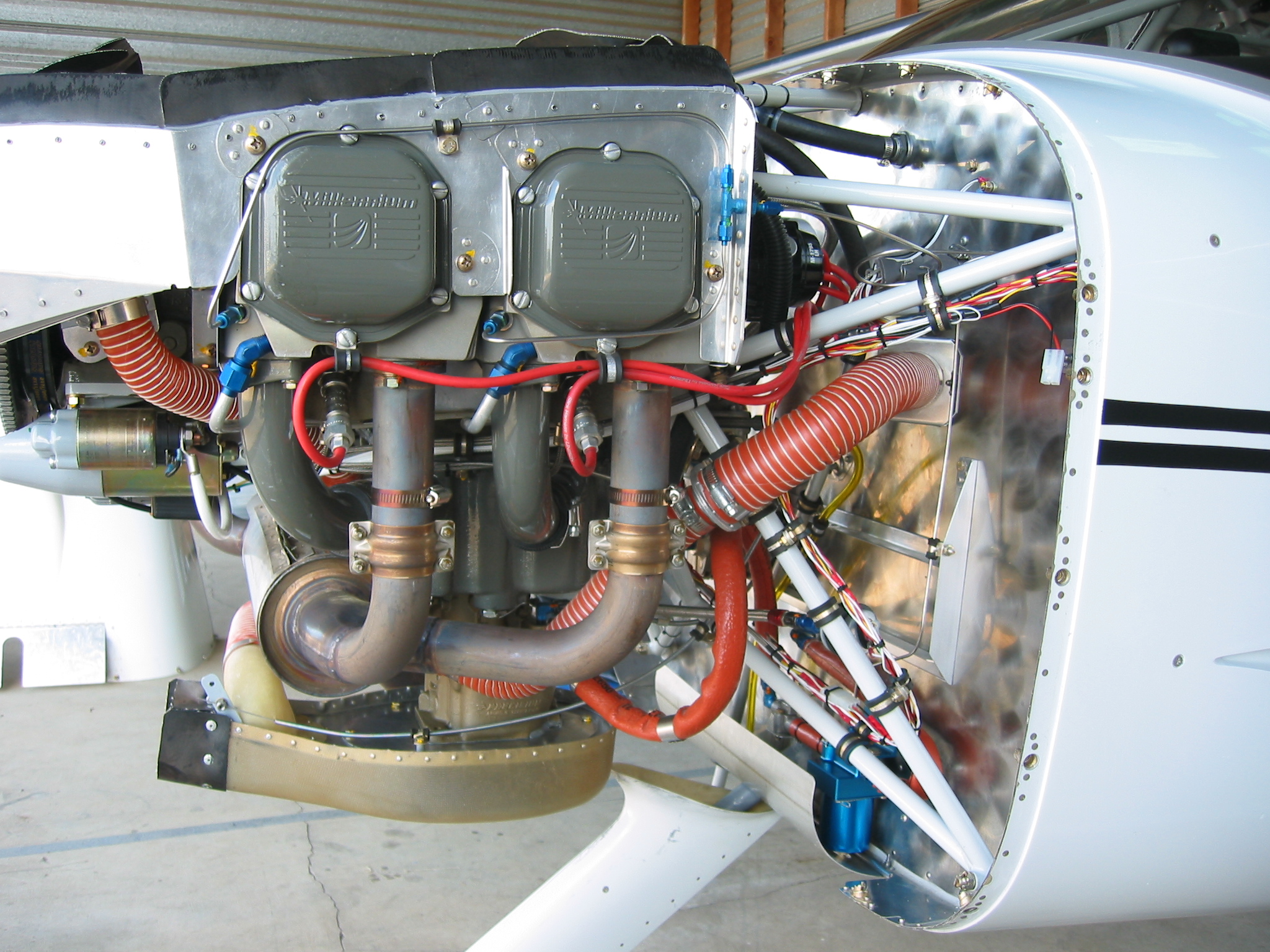
How to attach the Van’s air scoop to the GlaStar cowling: (Note, since I did this quite some time ago I am going to be “winging” it on some of this. Also, I had to do it twice, since I did not get it high enough the first time.)
- Mount the carb air box first or whatever air system you are using, so that you can get fairlyaccurate measurements for placement of the scoop.
- I installed an extension (net about 1.5″) all around the airbox to lower it, cutting a 2″ strip of aluminum and riveting it all around the perimeter of the air box and then to the mounting plate that mounts to the carb itself.
- The GlaStar cowl is such that you can install the scoop without all the foam spacers that come with the carb air box. I was able to just put a strip of the rubber baffle material around the front end of the carb air box (CAB hereafter), and it tucks right into the lip of the scoop and seals nicely. Note it will be pretty high on the cowl, and will be set quite deep, so the scoop is not going to stick out very far. Check out the picture of my plane on Sids net pictures.
- My engine is a Lycoming O-320 E2D. The measurements provided are from my engine. Measure your engine, and measure down from the prop hub then measure that on your cowl. (Mine came out 12.5″ from the prop hub to the upper edge of the scoop opening. (I figure you have about a tolerance of 1/4″ all four ways to maintain alignment.) You will also need to determine your fore and aft alignment measurements too.
- Lay the scoop on the cowl. Scribe around it. You will be cutting almost all the scoop mounting lip off, especially in front, in order to get it set in deeply enough.
- Once you have it laid out, take a big breath and cut out the opening in the cowl for the scoop. Set the scoop in the hole, align it the way you want it and fasten it. I ended up putting two pop rivets at the forward end, and one in each back corner (through the mounting lip and the cowl) to hold it securely in place. At this point you should have about an 1/8 inch opening all around between the scoop and the cowl, unless your scoop lip is still there and you can overlap it a bit. Mine was set in so deep that there was no lip left essentially except at the very aft end. Tape the seams on the outside with heavy package tape or 2 inch masking tape. Cut DBM tape to use on the joint. Do it in 3 or 4 pieces, as it does not bend around curves as well as the cloth does.
- Before glassing on the DBM tape, (this step is critical–I know because I had to do it over) You must completely fill the gap between the cowl and scoop with resin/flox/micro mixture or you will never get all the air bubbles out from under your tape resulting in a weak joint. Once that is down and still wet,then lay on your wet DBM tape (see my previous notes on wetting out cloth or tape between layers of plastic.). Let this cure.
- Now put a layer or two of regular cloth on the outside of the joint. Again fill any little holes or gaps with resin/micro mixture (Q-cell to S-H folks) before you put on your cloth. I would recommend putting peel ply on it if possible. It will make it a lot easier to finish later.
- Final finish, by filling holes or uneven spots (and especially around the upper fwd edge of the scoop) with your favorite light Bondo. Sand, sand, sand, and paint when you are ready. I also put on a layer of gel coat, but the color of the Van’s scoop is so far away from the S-H cowl, that I ended up painting the whole scoop to match the cowl/gel coat color.
–Paul Hansen
Carb induction: Carb. induction instructions, p. 18, step 7. The pre-cure laminate doesn’t need to be fabricated from scratch. When the induction housing is cut in step 5, drill some #40 holes on the line to insert a saber saw blade and cut the hole out neatly. save the cutout for step 7 it fits perfectly. Also, I think it is overkill to bond the laminate to the cowl and then laminate over the top of the air filter retainer ring. I skipped that step (20) saving time and weight.
–Ted Setzer
Van’s air induction system on a GlaStar: I am using an 0-320 E3D. I decided on the induction system based on price and performance. The S-H induction system has the NACA scoop in a low pressure area of the cowl and the air goes through a bit of swirling etc before going into the carb. The S-H induction system is also more expensive than the RV 6 Induction system. The RV system has a ram air scoop on the front of the cowl. The difference is that the S-H induction has directions etc to install and the RV has no directions for a GlaStar. It does have directions for an RV-6. So you have more work to do on the RV scoop but the performance is better. Note also that the exhaust from Vetterman is cheaper than the S-H exhaust but the Vetterman does not have a muffler so is a little louder, but not much.
As for props I have an Aymar-Demuth Prop. It is very light and has allowed me to mount the battery on the firewall. I could even put more weight ahead of the firewall and be ok. It is a wood IFR prop. I am surprised that there is even paint left on it after speaking with others who have wood props. I have been in some heavy rain and it has held up surprisingly well. The paint is not even starting to come off.
–Rhett Westerman


