 C/C inter-bulkhead shearweb: If you follow the manual when doing the C/D inter-bulkhead shearweb, you won’t have any picnic when placing the DBM side flanges. Instead, make a sandwich. Use a piece of scrap about 10″x1″ for the bottom slice of bread, the DBM for the meat and the shearweb for the top slice. Drill the 2 aft holes on each side thru the scrap, using the shearweb as a template. Butter the bread, smear mayo on the meat and slip it in halfway lengthwise, leaving about 1-1/2″ hanging out. Toothpick (cleco) the bread thru the 2 holes on each side and fold the meat down so the sandwich will fit into the fuselage. Don’t forget to put resin on the fuselage, put the sandwich in and stipple the DBM to the fuselage thru the inspection hole you cut on the bottom. When cured you can remove the clecos and save the scrap. And now you know where the other missing sandwich is D/E inter-bulkhead shearweb!
–Don Hatler
Bulkhead C & D shearweb: For the shear web between bulkhead C and D: I would strongly recommend that you put nut plates on the attach DBM tape (as in the shearweb between D and E), including on the small angle brackets on the aft side of bulkhead C. ( I just spent 10 man-hours mounting that shear web – next to impossible because you are working over the elevator pushrod, over the rudder and elevator horns, etc. trying to put on nuts) Also on the same brackets (.063 aluminum angle on aft of bulkhead C) Do not put the holes for the bolts in line with each other. Offset them, (make the bracket longer if necessary to accommodate that) Otherwise the bolts attaching it to the bulkhead interfere with putting in the bolts for the shearweb.
–Paul Hansen
Shearweb between bulkhead C & D: When you install the fiberglass support for this shearweb, after drilling holes for the bolts, install nutplates all around. I did not initially, and it took two of us 5 hours to install it the first time. It is very difficult to get up there and work through the inspection hole and around the elevator horn and pushrod to install nuts on bolts. I recently had to remove it (which took two of us 2 hours!) Solution? Install nutplates in that fiberglass support. For the fwd attach points put the 4 nut plates in the shear web itself, as it fits under the two brackets on Bulkhead C. The fwd 3 holes on each side are under the curvature of the fuselage sides and you cannot rivet on a regular nut plate there, either by squeezing or driving. I installed floating nut plates there using hardware store epoxy and using an AN3 short bolt through the hole to hold it in place while the epoxy set up. This way one person can install the shear web from the top by simply screwing in the bolts in just a few minutes.
–Paul Hansen
Shearweb inspection hole:The “inspection hole” is misleadingly named, as its main purpose is not to provide access for inspection but rather for laying up the side attach flanges for the shearweb and for installing the nuts on the shearweb attach bolts. There’s nothing wrong with using nutplates here instead, but we couldn’t figure out (as someone on the net mentioned) any easy way to rivet nutplates for the forwardmost pair of holes on each side. If you figure out a way to do that and if you prefer to use a laminating former with a hole in the middle (like the one we describe for the aft shearweb) then feel free to eliminate the inspection hole.
For annual inspections and the like, we recommend removing both the forward and aft shearwebs. (See the Handling, Service & Maintenance section of your Owner’s Manual, which.) You will be able to do a much more thorough inspection of the rudder control yoke hardware and the elevator bellcrank from above with the shearweb removed than from below through the hole.
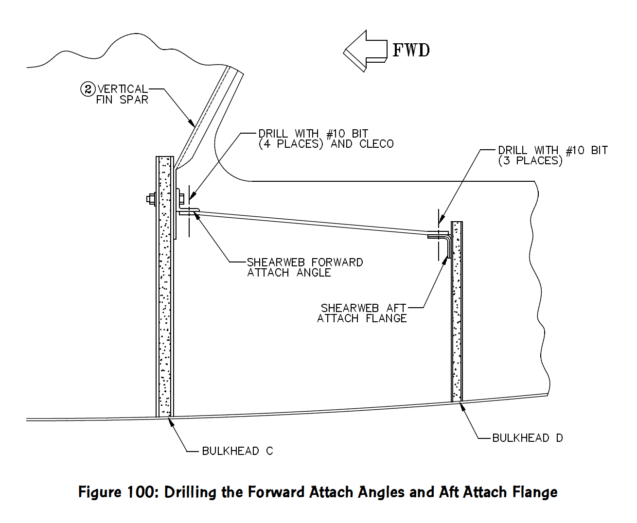
As for fitting the shearweb, I’m frankly not sure why this has been such a big issue for some of you. On the several GlaStars I know about personally, this simply has not been a problem. However, one possible source of difficulty may arise if you have neglected a couple points made in the ANOR of 2/18/98 (see Page 5). This called for increasing the width of the forward shearweb aft attach flange to 1-1/2″ from 1″ and for decreasing the length of the shearweb by a corresponding amount. This is necessary to allow the shearweb to be installed and removed with the stabilizer attach bracket in place.
–Craig at S-H
Installing the forward shearweb: In keeping with my goal of not drilling a large hole in the bottom of the aft fuselage, I have a suggestion for Laminating the side attach flanges for the Forward Shearweb. Ref. Step 73 p. 137: Instead of using the entire underside of the shearweb, make a duplicate panel (I used some .032) and cut it in half or even in thirds and use the outside pieces to support the laminating of the DBM flange. This way you can get underneath the (simulated) shearweb from the top . After it cures, remove the alum. piece and cut/trim it to about an inch wide. Drill the attach holes thru the flange and .032 backup plate and use this plate to attach some nut plates. Attach the nut plate assembly to the web with some resin, structural adhesive, T-88 or whatever you like to keep it in place. This .032 strip with nut plates (method) can be applied to other locations as well.
–Jim Rose
Installing nutplates on the shearweb: Let’s see if I can explain what I did.
- Configure the shear plate to fit the area between bulkheads C & D.
- Establish the four rivet holes (per side) and drill them using a #30 drill.
- Use some .032 sheet and make a one-inch wide strip that follows the outside (fuselage flange) curve for at least the length of the four rivet holes and comes flush to the inboard edge of the laminate flange. In other words, a strip that matches the Laminate flange.
- Place the formed strip under the newly made shear panel and “match drill” #30 the strip – 4 places.
- Cleco the strip under the laminate flange using the two aft holes for indexing.
- Using two 90 degree drill units connected together (one electric and a mini slave 90), drill through the template hole and into the laminate flange (2 places).
- Open the holes to #10
- Use the “transfer strip” and rivet nut plates to all four holes.
- Bond the strip assembly. to the underside of the laminate flange using 3M structural adhesive, T-88, resin/micro etc. I used the 3-M as it bonds almost anything to anything (and is left over from the KitFox project).
Believe that will do it. Boy, do I have a respect for Craig and the manual writers. I am sure he/they could “clean” this up and really make it simple to understand.
–Jim Rose
Installing nutplates on the shearweb clarification: The fiberglass side angles are installed in a similar manner as the ones for the aft shear bulkhead plate (D to E). Hot glue did a fine holding job. Mold release was used on the plate. This “working plate” also established the bolt hole pattern . All holes on each side were located and drilled through the plate and the .032 by 1-inch wide strip. The strip became a “transfer strip” or hole duplicator strip to locate the forward two holes. (Using the aft two holes to index the strip for drilling the forward holes). These (forward two holes) were drilled from the bottom side of the formed angles. Then the strip became the nutplate holder and attached (use a good epoxy to bond it) to the underside of the formed flange(s). The real plate was formed and the “plate” pattern again located the holes.
–Jim Rose
Elimination of fuselage hole in tail section: Here is another method to eliminate the fuselage hole in the tail section:
- install the D bulkhead and F glass bracket as in the manual
- install the forward attach alum. angles to Bulkhead C as in the manual
- fit shear web between the two and hold in place with clecos
- draw lines along the sides the of the fuselage at the top of the shearweb.
- put duct tape below the line on one side.
- hot glue a thin metal “L” on top of the shearweb to the fuselage side
- remove the clecos and let the shearweb fall down and to the side in the tail cone. It’s tight but can be manipulated somewhat out of the way.
- Cleco a 1.5″ wide x 9ish” long 0.050 waxed aluminum strip to the bottom of #6. This will simulate the thickness of the shearweb.
- Layup the 2 x DBM strip in the corner between #8 and the duct tape.
- Let the new F Glass Angle cure, mark the two aft holes and then release
- Do the other side in the same manner. Remove the duct tape from both sides.
- Drill the two aft holes in the F. Glass angles where you marked them in #10, cleco these 2, drill and cleco the forward two. Install the 8 nut plates on the sides
- Put in all 8 little bolts just barely to allow lots of movement between the shearweb and F. Glass angles. Slide the whole contraption into place, cleco front and back and tighten up the bolts for a test fit. Take a little mirror and peak through the “U” cutout in the front of the shearweb to ensure that your F. Glass angles are fitting perfectly against the sides of the fuselage. Remove the fixture.
- Prepare fuselage surface and F. Glass angles for permanent installation with resin and some mill fiber ( to add viscosity while installing)
- Apply the thick resin /mill fiber mixture to the side of the fuselage and F. Glass angles.
- Slide in the shearweb / F. Glass assembly with the bolts very loose as before.
- Cleco the front and back and tighten all 8 bolts as before. Let cure. Remove shearweb. I put a bead of resin and millfiber in the round corner between the F. Glass angles and the Fuselage to firm them up. It did.
- Put nut plates on the front of the shear webb and the rear F. Glass angle.
- Corrosion-proof and you are done.
This method may seem a bit pain full but will not compromise the structure in this key area with a hole. The shear plate is easy to remove for a proper inspection. Seven of the 15 bolts can be removed with a power driver. Hope this helps.
–Bill Baxter


