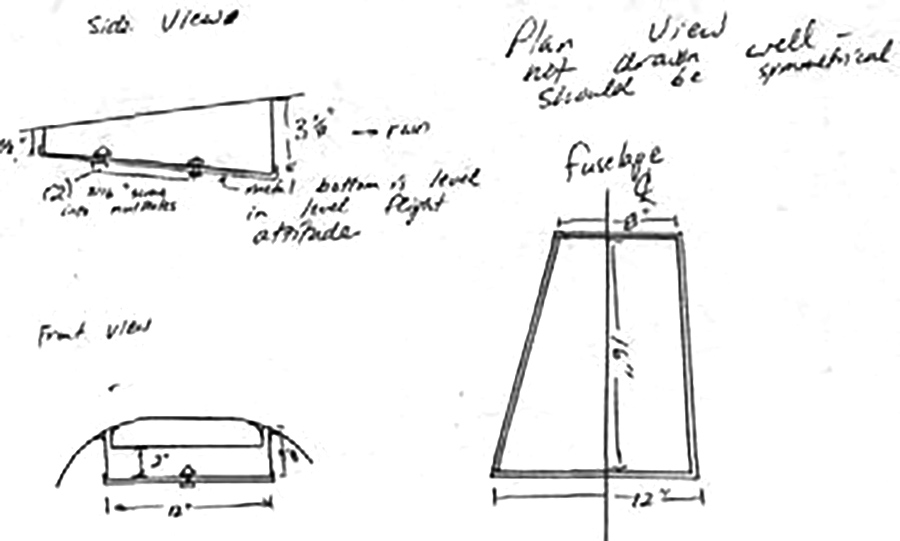
Here are a couple of quick drawings for my overhead GPS antenna tray.
- Produce side walls from 1/4 inch foam, coat one side with Q-cell and a 2 layer laminate. This will be the inside. Bond the walls together with Q-cell mixture. Lay saran wrap down and bond together inside the fuselage (inverted) if possible to assure perfect fit. Use Q-cell and a 2 layer laminate to fix the corners.
- Lay down saran wrap and peel ply on a work table, and make a flange at the bottom of the structure. Cut off about 3/4″ diagonally at the corners and use a sheet metal brake to bend a flange outside the edges of the fiberglass structure.
- Coat the outside of the walls with Q-cell and a 2 layer laminate.
- Obtain a piece of sheet aluminum (.020 to .032) and mark 1/4″ outside the size of the bottom of the structure. Cut off about 3/4″ diagonally at the corners and use a sheet metal brake to bend a flange outside the edges of the fiberglass structure.
- Drill the metal bottom in six places about 1/2″ inside the bend lines for screws and use the bottom as a drilling guide to drill through the fiberglass flange on the bottom of the structure. Install nut plates on the flange using countersunk rivets and standard technique.
- Remove the metal bottom and bond the structure into place in the fuselage using standard Q-cell radius and edge laminate technique.
This clearly would be much more difficult with the fuselage upright, so I installed this prior to installation of the tail.
Advertisement