This tip was submitted by Kurt Rutkowski, Glasair Super II RG.
Due to the composite construction of the Glasair, there is no need to use conventional, external, drag-inducing antennas. Therefore, the builder may wish to construct his own zero-drag, high-performance antennas. The embedded dipole antenna is preferred for two reasons. First, it is bonded to the inside of the fiberglass skin, which adds no drag. Second, the dipole antenna requires no ground plane. Conventional metal aircraft use the metal skin as the ground plane.
One of the disadvantages of the dipole antenna is that the required length of the radiating elements is half a wavelength, twice as long as the quarter-wavelength antennas used in conventional aircraft. Another problem is that the dipole antenna has an impedance of 75Ω versus 50Ω for the 1/4λ antenna. (Ω = omega, the symbol for Ohms; λ = lambda, the symbol for wavelength). Aircraft radios are all manufactured to be connected to 50Ω antennas using 50Ω coax cable.
Basic laws in electronics say you will get maximum power transfer to or from the antenna when impedances are matched. Therefore, you will get the best transmit and receive performance when all impedances are equal. The radio’s impedance is 50Ω and the cable’s is 50Ω, so the antenna’s should also be 50Ω.
However, the impedance mismatch can be overcome. The 75Ω dipole antenna can be made to appear to have a 50Ω impedance by adjusting the coax cable length to create a 360°/180° phasing at the feed point of the antenna. Without getting into a long, complicated discussion of wave-propagation theory, I will just tell you that this can be accomplished by cutting the coax cable in half-wavelength increments.
In order to determine the length of a half wavelength, two factors must be considered. First is the frequency of the signal to be transmitted or received. Second is the velocity factor of the cable in use. If a band of frequencies are used, use the center frequency of the band. The formula to determine1/2λ in space is:
1/2λ (ft) = 468 ÷ frequency (in MHz)
i.e., to determine the 1/2λ of 127.5 MHz (center of the COM band):
1/2λ = 468 ÷ 127.5 = 3.671 ft or 44.05 in
The velocity factor must be considered now due to the construction materials used in the manufacture of the cable. RG 58A/U coax and Belden 9222 triax cable have a velocity factor of 67%. Multiply the1/2λ by 0.67 to determine the physical length of the cable to equal 1/2λ electrical length, i.e.:
physical length = 0.67 × 3.671 ft = 2.459 ft or 29.51 in
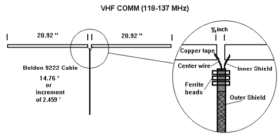
Therefore, the cable must be in an increment of 2.459 ft, e.g., 6 × 2.459 ft = 14.76 ft. If the cable needs to be shorter or longer than that, it must be done in 2.459 foot increments.
To determine the lengths of the radiating elements the same two factors must be considered: frequency and velocity factor. The frequency will be the same as determined in the cable calculation, but the velocity factor will be different. If you use half-inch copper tape, the velocity factor is 95%. Therefore, apply the same formulas to compute the element lengths, but replace the velocity factor of 67% with 95%:
1/2λ = 468 ÷ 127.5 = 3.671 ft
physical length = 0.95 × 3.671 ft = 3.487 ft or 41.84 in
This is the total length of both elements. This must be divided by two to determine the length of each element. In other words, each element must be 1/4λ.
3.487 ft ÷ 2 = 1.744 ft or 20.92 in
Three ferrite beads should be placed on the cable as close to the elements as possible. This helps suppress reflection currents in the shielded cable to help reduce standing waves in the cable. After the ferrite beads are positioned, I used heat shrink tubing to hold them in place. RTV caulking will also work. Then solder the inner shield and center conductor to the copper tape elements as shown. Keep these wires as short as possible and do not allow them to touch each other. If using triax cable, the outer shield should be left unterminated at both ends. Trim back and shrink the tube over the end.
Materials required to construct this type of antenna are as follows:
- Triax cable (Belden 9222 50Ω or equivalent)
- Copper foil tape (1/2″ 3M tape (P/N 1181) used in this example)
- Ferrite beads (Fair-Rite P/N 2643002402)
- BNC connectors
- Soldering iron and a knowledge of soldering
- 1/4″ and 1/2″ heat shrink tubing
A finished COM antenna is shown in the figure below.
Cable and element lengths for aviation antennas are as follows:
| Antenna type | Increment | Length |
|---|---|---|
| VHF COM (118–137 MHz) | 2.459 ft | 20.92 in |
| VHF NAV (108–118 MHz) | 2.775 ft | 23.61 in |
| Marker Beacon (75 MHz) | 4.181 ft | 35.57 in |
| Glide Slope (329–335 MHz) | 11.33 in | 8.035 in |
In conclusion, be accurate in cutting the cable and radiating elements, particularly in the higher-frequency antennas. Small errors in length will have a greater effect at the higher frequencies. Follow your Glasair Instruction Manual for the proper location and positioning of the antennas.


