Submitted by John Schroeder
This is a supplement to the Builder’s Hint published by Neal Garvin describing a new way to align the hinge brackets on the spar of the horizontal stabilizer. I found this method to be an excellent way to do the job, but would like to describe a problem I had and how it was fixed.
When I first set up the two blocks and strung the fishing line between them, things seemed to be going great. Neal’s & Hal’s article was easy to follow and it is an easy setup. John Burnaby graciously made me the three bushings needed to make a complete alignment jig.
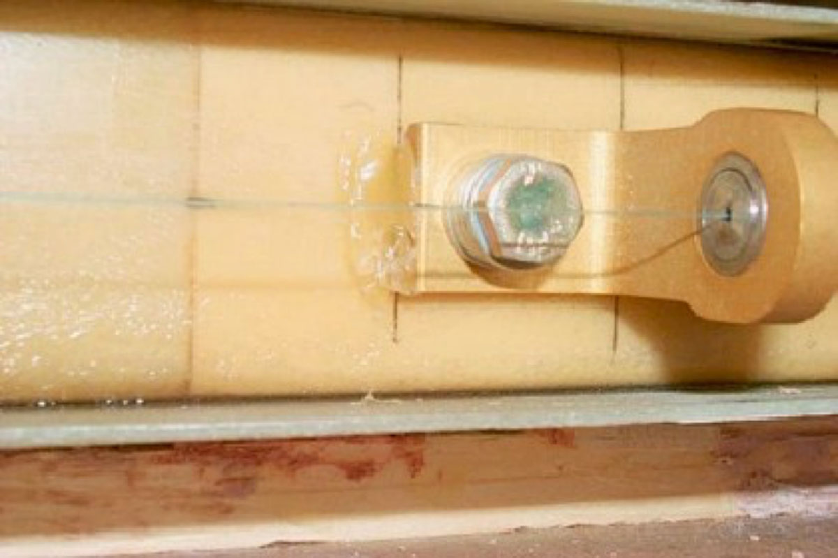
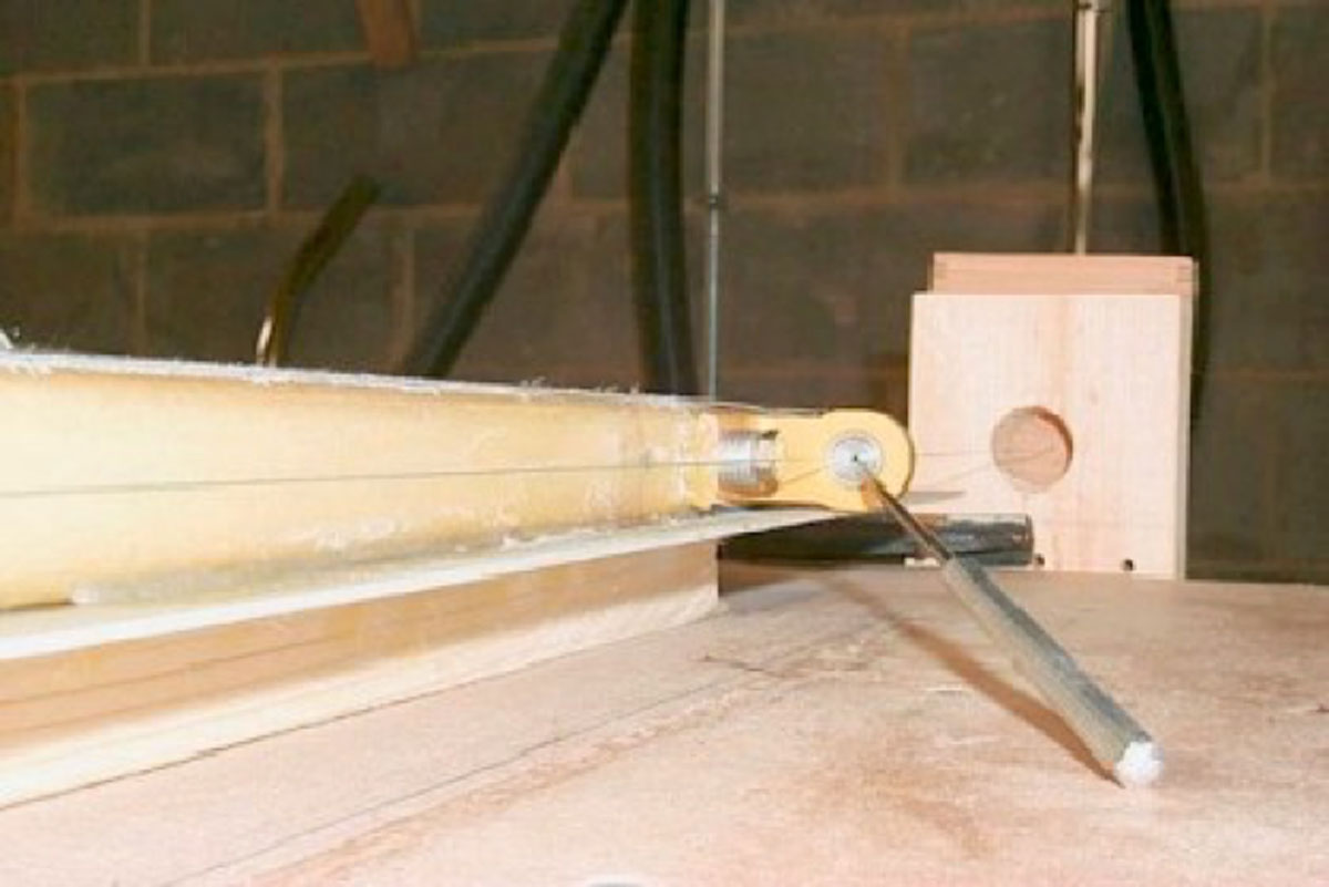
The pictures below show the basics of Neal’s scheme. The first is shown without the bottom skin installed.
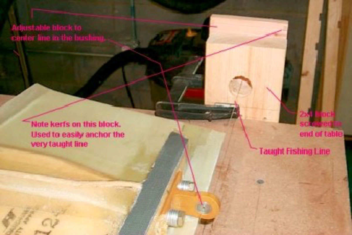
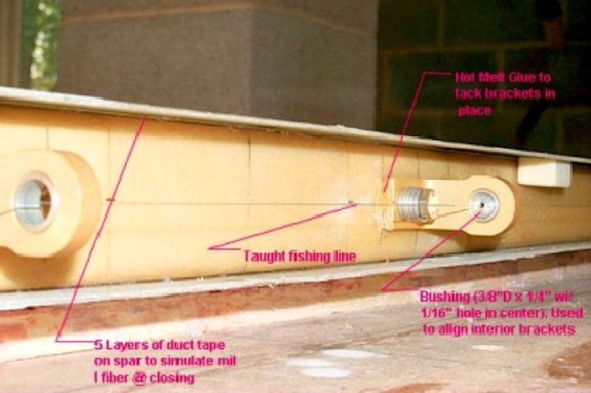 After tacking on the two outboard brackets so that they were equidistant between the top and bottom skins, I started aligning the 4 interior brackets and tacking them in place with hot glue. The problem was that the two mid brackets were above the centerline of the spar by about 3/32″. The two interior brackets were a tad over 3/16″ above the centerline. In a posting, Neal suggested a few possibilities to me. One was that the whole spar-upper skin structure might be too low in the middle of the v block jig. I called Cal at S-H. He agreed and suggested shimming the upper skin off the v block by 3/16″ under the two interior hinges and then distributing the remainder out in each direction until it was 0″ at the two outboard brackets.
Photo 3 shows the shims. Once the shimming was done and I filled the gaps as much as possible with bondo to prevent sags, the 4 brackets were aligned and temporarily fastened with a band of package tape from the top skin to the bottom skin. I rechecked the alignment on all four hinges and hot glued them to the spar.
 Before drilling the holes, I called John Burnaby to seek counsel. He also had sent me a long list of suggestions and I wanted to cross check the fix before drilling. The problem appears to be that the v block may be too deep in the middle – if the thickness of milled fiber, simulated by the 5 layers of duct tape on the non-bonded face of the spar cap and the actual thickness of the bond between the cap and the upper skin in the jig are less than the nominal value allowed by S-H when they drew up the plans. If this turns out to be the case, you will have to shim like I did.
The remainder of the pictures are other shots of the Garvin process. I might add that I did not have to shim any of the brackets out from the face of the spar or shim at an angle so that the distances between skins and the boss of each bracket were equal. The spar was straight and not warped at all. I attribute this to using John Burnaby’s jig for holding the spar in place while bonding it to the jigged (upper) panel. It does not take that much time to make. I posted a couple of pictures of it already.

