I conduct most of the Phase 1 initial flights on Sportsman aircraft that are born out of the TWTT program. Even though I am on my toes on every first flight, they typically are routine thanks to the meticulous work done by customers and their customer assembly center guides.
The most excitement I’ve experienced on a first flight was when an engine sputtered and died when the fuel gauge showed over 10 gallons in the main tank. The left tank was selected 30 minutes earlier after the right tank showed nearly empty. When an aircraft engine dies unexpectedly, you must not be human if you don’t experience momentary panic. Once past the surprise, the training takes over: turn the nose for the field, hit the boost pump and switch to the “empty” tank. After an agonizingly long 3 seconds, the engine sputtered back to life and the emergency was over. It turned out that the sending unit wires for left and right tanks had been mislabeled on the wiring harness. Murphy’s Law wouldn’t have it that something uneventful like the position light wires would be mis-marked right?
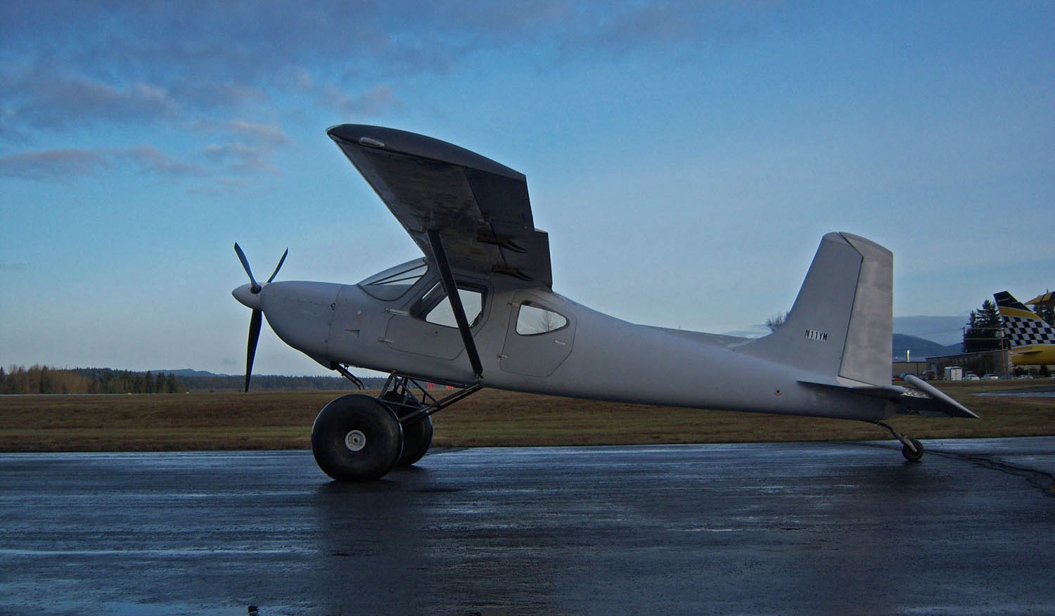
In spite of my first flight experience, when the day finally arrived for me to saddle up N11YM, I was a bit surprised at how genuinely nervous I was.
I’ll admit that all those lightening holes and dozens of other modifications I was to rely on were about to be put to a real world test, but there were a lot of other modifications all to be tested at the same time. There was no way to separate them and deal with them one at a time.
With a new engine (or rebuilt engine in my case), the primary objective is to get the piston rings to seat properly. Limiting any unnecessary taxi time and engine idle is very important, so I conduct the EFIS generated pre-take-off checklist on the roll toward the active runway. Once the oil temperature is over 80°F, I launch with everything to the firewall and keep it there.
The modifications
In the case of N11YM, there were so many thoughts about the modifications going through my brain it was hard to concentrate on the engine only. Here is a list of the significant changes:
- Wet wing with different brand of selector valve and electric fuel pump.
- Fabric control surfaces.
- Larger, fabric flaps.
- Straight vertical tail vs. swept tail.
- Longer cord stabilizer, shorter cord elevator with centerline hinges.
- Mechanical elevator trim.
- Ailerons displaced 1.0” farther aft.
- Modified aileron bellcranks and an additional aileron servo tab.
- Swiss cheese outboard wing spars.
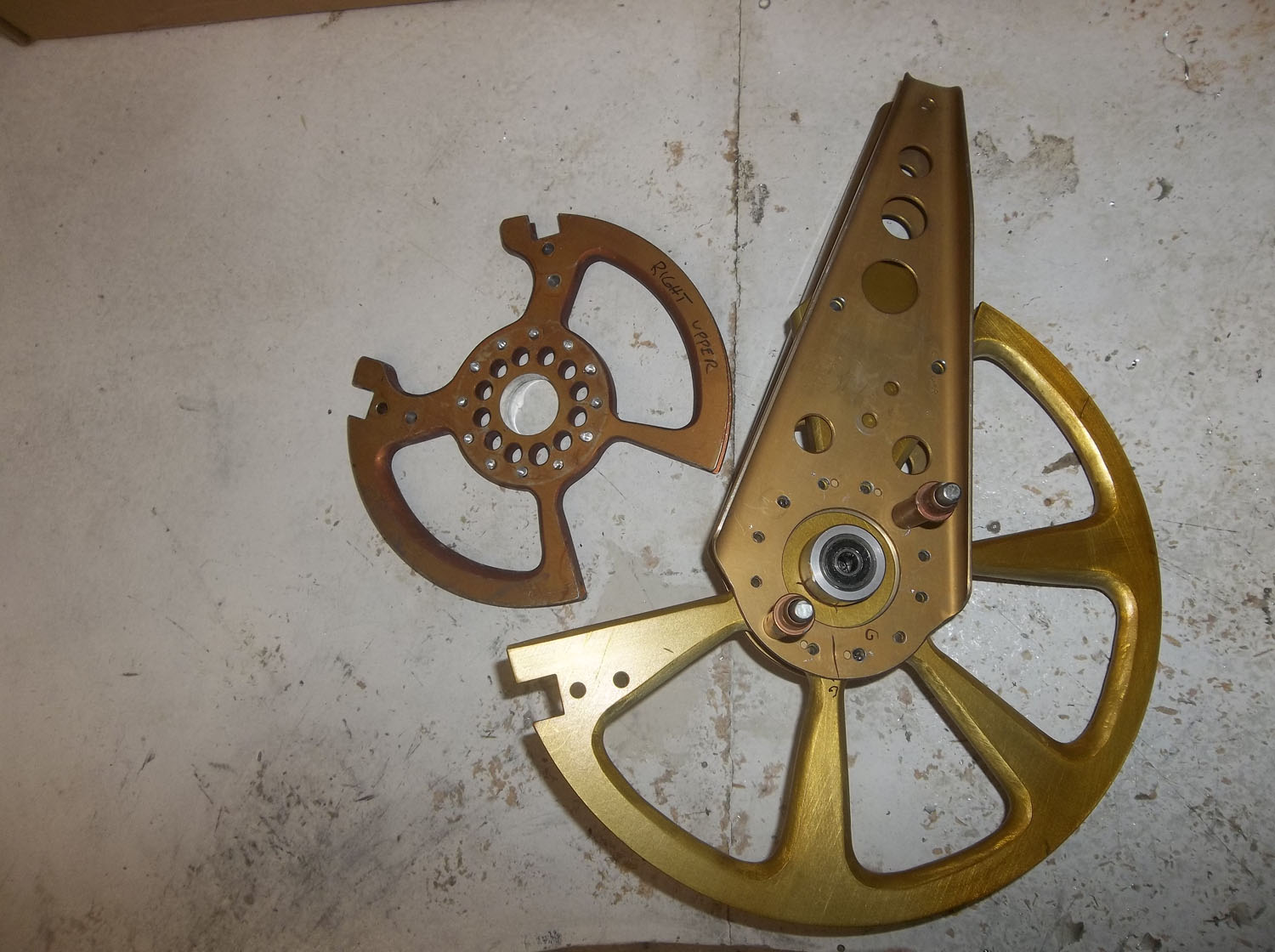
- Swiss cheese everything else I dared taking weight from.
- Major Swiss cheese on the starter ring gear.
- Customized induction sump with a “pop-off” pressure relief valve machined by my brother, Mike. It wasn’t his machining I was worried about, but rather, the function of the self-designed valve. Search Ryton sump problems on the Internet and you can find out why I wanted a pressure relief valve on this lightweight sump.
- Stroker crankshaft with 9.3:1 pistons.
- Dual Lightspeed Plasma III electronic ignition system.
- Self-made landing gear (previously flown).
- New oil cooler location and air source.
- Lithium Iron-Phosphate battery (It didn’t help that Boeing was reporting meltdown of theirs).
- Rebuilt governor.
My engine is a former test cell engine from Lycoming. As such, I had to fabricate a special fitting to mount on the front governor pad to deliver the high-pressure oil to the prop from the aft mounted governor.
Twice I had to abort takeoff because I was getting way too much RPM for the corresponding power (manifold pressure) according to the RPM reading on the EFIS. I thought I had a bad governor, but after switching to a new governor, the issue persisted. It turned out that it was simply an rpm calibration adjustment made in the EFIS! I borrowed a dash mounted prop tach and confirmed the EFIS RPM finally agreed with the engine.
On the third takeoff attempt I brought the power in slowly and noted the static RPM as I reached lift-off speed. Since any new governor might be set incorrectly, I am very careful to avoid a prop over-speed on the first takeoff, plus it allows me to make a governor adjustment if necessary once back on the ground. Finally airborne, I needed to concentrate on what I always prioritize on first flights: Aircraft controllability and engine health.
In the case of N11YM, the controls were deemed acceptable as I climbed to 2,500 feet so I shifted most of my attention to the engine gauges and my senses: smell, sound, touch, etc. Any sense of smoke, fuel or heavy oil smell and I’d be immediately heading back. Thankfully, 1YM smelled, sounded and felt normal. After leveling off in a race track orbit over the field, I began to scan the panel for things that may be non-functioning or erroneous while not taking attention off the Oil Pressure, Fuel Pressure, CHT, Oil Temp, EGT and Electrical. (Note the order of importance)
Engine break-in
I break in all engines the same: Wide open throttle (WOT) and maximum RPM to create high pressure with the rings against the cylinder walls. Heat also helps with seating the rings, so CHT on the high end of the scale isn’t something to avoid. The Lycoming parallel valve engines (180 hp) produce much higher CHT during break in than do the angle valve IO-390 engines. For cooling purposes, the 390 series engines use oil nozzles that squirt oil against the backside of the pistons. I don’t understand why, but the parallel valve engines lack the nozzles. I installed them on my engine and was expecting and received lower CHT than a stock engine. A standard parallel valve IO-360 engine typically will produce 400-450° CHT during break in at high power settings, which is desirable. The IO-390 CHT is typically in the 285-340° range; a bit too low for break-in. For those of you breaking in an IO-390, consider temporarily closing off the cowling air inlets by 25% with duct tape to increase CHT closer to the 400° range.
Lycoming recommends not continually running the engine at the same power settings during the entire break-in, so I reduce power periodically to 24 squared or 25 squared but the best results I’ve experienced is to spend the majority of my flight time in the first 3 hours at full MP and RPM.
If you follow these procedures, the engine rings will seat pretty well within the first 5 hours. Keep in mind though that a typical ring seating graph looks like an inverse or decreasing exponential curve. The curve is very steep at first but gradually flattens out over time. It can take up to 100 hours or more for the rings to fully seat so don’t be in a hurry to change from straight mineral (break-in) oil until you pass the 100-150 hour mark. You can certainly back off from WOT all the time, but I slowly transition to reasonable power settings over time and keep mixing up the power settings.
After 5 hours, doing pattern work and practicing touch-and-go landings is fine and a very good way to mix up power settings.
The indications to look for to determine if the rings are seating are a reduction and stabilization of both CHT and Oil Temp and over time, oil consumption will stabilize so be sure to make a note of these temps at a given power setting on the first flight and log all oil consumed. Do not run more than 6 quarts in the engine or it will quickly blow out the breather, make a dirty mess on the belly and give you a false sense of oil consumption.
I try not to stay in the air more than 45 minutes to one hour on the first flight. I landed 1YM after an exciting 60 minutes with the following initial results:
- Wings nearly in trim; no heavy wing.
- Minor rudder trim necessary. (Only the lucky need no rudder trim).
- Oil consumption less than 1/8” on the dipstick.
- One minor oil leak on the governor mounting pad.
- Minor EFIS squawks.
- Engine temps all in the green and the engine ran great!
- Static RPM on takeoff was 2750.
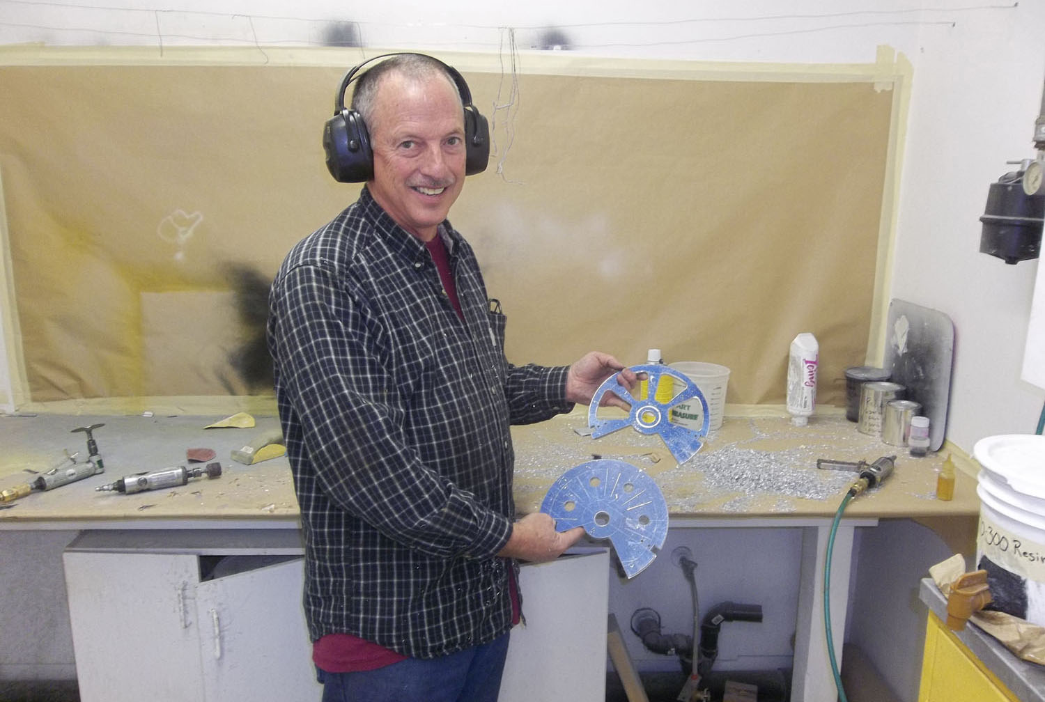
one-hour per hole to carve by hand. Just about in-line with my docemented average of 10 hours per pound.
Results of the modifications
So, how about the results of my modifications?
The wet wing fuel capacity is 74 gallons! I noticed that the fuel levels on the gauges varied a lot indicating that I need additional baffling in the tanks. When I remove the wings for paint, I will open an inspection hole at the mid-point of the tanks and restrict the span-wise fuel sloshing by covering some of the rib lightening holes. Rats, now 1YM will gain 125 grams more in weight.
The elevator feels the same as a stock Sportsman. But, I removed so much weight from the tail surfaces and counterweights that I can’t meet forward CG limits when flying alone and low on fuel. Double Rats! I will have to add 4 lbs to the tail cone to compensate or drill lightening holes in the spinner and prop blades.
The fabric all stayed attached to the flaps and control surfaces. Yes!
Rudder authority was excellent.
Mechanical elevator trim needs some refinement. There is too much play in the inner wire.
Aileron forces are way too light. At first I thought this was the result of having lighter outboard wing sections, but Paul Robertson said it is the result of my having displaced the aileron hinge points 1.0” farther aft. So, on subsequent flights, I removed one of the servo tabs and even reduced the travel on the original one to obtain optimal roll forces.
The induction sump held together and the pop-off valve worked fine. “Fine” in the sense that if the O-ring wasn’t sealing, the engine would be experiencing a significant induction air leak and exhibit a rough idle, but this engine with E-ignitions idles VERY smooth.
The IO-375 Stroker-crank with high compression pistons nets nearly the same hp and performance as the IO-390. Very Impressive.
The Lightspeed electronic ignitions are a dream. Smooth running. I experience only a 20 rpm drop when I isolate the ignitions on pre-flight.
The landing gear worked fine, albeit for only one landing.
The Lithium battery was fine. Phew! At the last minute I exchanged the 60-amp alternator for a B&C 40-amp alternator with adjustable voltage regulator. From what I’ve read the biggest cause of lithium battery problems is over-charging. The manufacturer warns not to allow the battery to charge at over 24 amps. The battery technical info page mentions that if you drop the output voltage on the voltage regulator from 14.4 to 14.3 volts it will double the life of the $350 Lithium battery. I made an adjustment to the B&C regulator and it settled in at 14.2 volts.
Maybe I will quadruple the battery life? I’ll need an electrical engineer amongst the GlaStar/Sportsman community to steer me right here. I’ve learned a lot so far, but plan to learn a lot more about the Lithium battery in the future. For anyone considering it, take the advice I received very seriously: Use only a Lithium IronPhosphate battery. These do not build heat nearly as bad as the Lithium-Ion type. Also, you need to understand the battery chemistry and what causes heat to build.
Lastly, the flaps were a big disappointment.
In fact, to be perfectly honest…they were virtually useless initially.
Flaps gone wild
I was warned more than once by my friend, Paul Robertson of Aeronautical Testing Services to approach deployment of the flaps very slowly and cautiously. If the larger flaps were to produce a blanking effect on the tail, the tail would stall and the plane could go out of control. He also warned that high flap pressures may hinder or prohibit retracting them once deployed.
My brother Tom who was lead engineer and designer of both the GlaStar and Sportsman was concerned that the fabric flaps may not be as strong as the metal ones. I heeded his advice during the assembly of the flaps and doubled the spar thickness and doubled the number of ribs. These guys had me well freaked out about testing the flaps. It turned out to be sound advice.
After breaking in the engine rings for 45 minutes I wanted to at least sample the big flaps before returning. After climbing to 3,500 ft and slowing the plane down to 70 kt, I very slowly and carefully pulled on the flap handle but it took a LOT of force just to get to 20 degrees. I tensed up my arm and slowly budged it off 20 degrees but when it got somewhere between 20 and 35 degrees the pressure suddenly reversed and it literally slammed to the back of the tracks with a loud BANG. There is no way I could have stopped it, and it was a very fortunate thing it didn’t blank out the tail because it was a difficult two-handed job to retract the flaps off the 35° position, in fact, I couldn’t retract them at all until I had reduced the airspeed to below 60 kt.
I had to try it one more time before I landed to be sure I wasn’t dreaming. Yep, I confirmed a second time that the flaps were a mess and it momentarily overshadowed all the other things that had gone right on the flight.
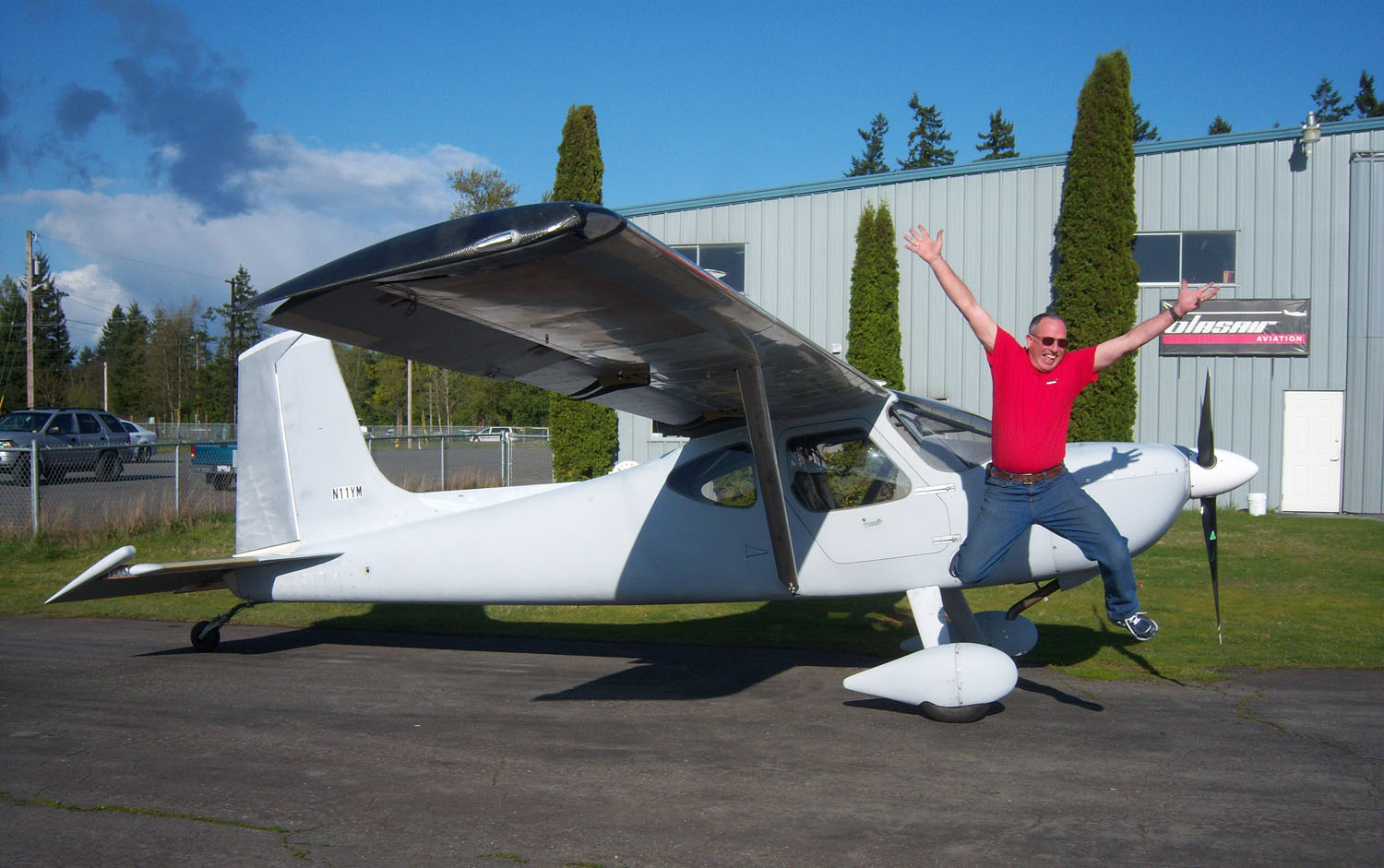
I landed and taxied up in front of a medium-size crowd of supporters that included Kari, my parents, friends and many employees of Glasair Aviation. I popped out of the cockpit with a big smile on my face.
Despite the disappointing flaps, the flight was, in fact, a huge victory representing 5 years of fabrication and assembly effort for me and many others who had helped me along the way. It was time to take pictures and celebrate the moment. Fixing the flaps would have to wait…
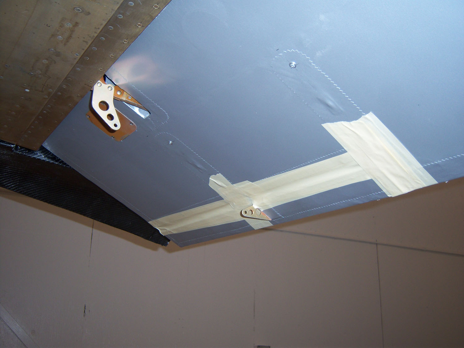
With help and advice from the ever generous Paul Robertson, we put yarn tufting on the right wing and flap and aft fuselage and bottom side of the stabilizer and attached two GO-PRO cameras to the fuselage and conducted a series of flight tests to observe anything amiss with the airflow over the flaps or aft fuselage (see testing video below). While nothing out of the ordinary was seen, Paul suggested we could optimize the gap between the wing skin upper trailing edge and flap in the full flap position by adding a ½” trailing edge extension. After doing this, I detected a very slight improvement, but much more remained to be done. He said the flap tracks would likely need to be re-designed. It boiled down to two things:
- The forces were way too high and
- Something strange was going on to cause the force reversal. The strange part I will have to rely on Paul to solve but I thought I might be able to deal with the forces.
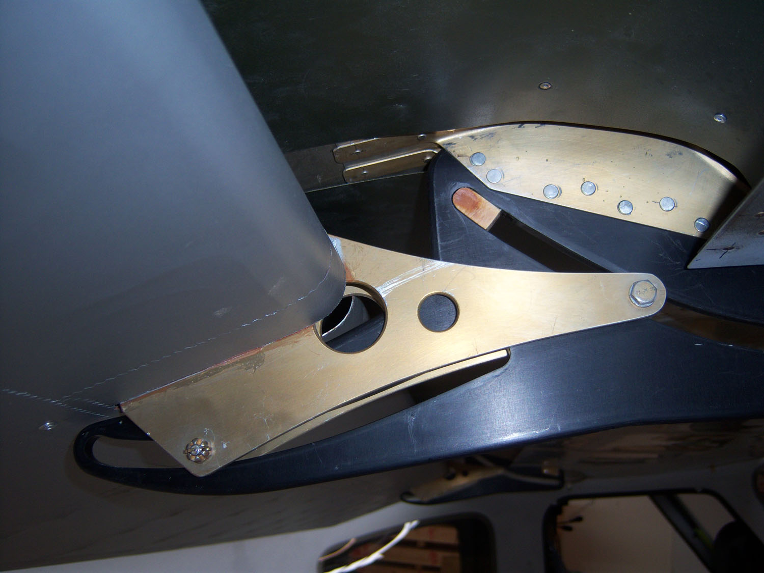
I opened up the inspection holes and studied the flap pulley and bellcrank arrangement. Since my flap tracks were 1.75” longer, I had simply lengthened the bellcrank arms by 2” or so to get the extra push-rod travel needed. It suddenly hit me between the eyes: I lost a ton of leverage by extending the arms without extending the diameter of the flap pulleys by the same amount. But now I had to fix all of this by opening up sections of the flap cove skins, drilling the brackets from the aft spar, removing everything, making all new parts and reassembling it all back inside the wing. I had a plan, but it wasn’t going to be easy.
My brother Mike came to the rescue and machined me two beautiful nine-inch diameter aluminum pulleys. I spent one entire day drilling and grinding off all the unnecessary aluminum (some habits are hard to quit) and began the task of fabricating new brackets, drilling the old parts out and installing the new ones. TWO TIMES I installed the new pulleys and brackets and failed to get proper alignment with the cables. Finally on the third attempt after a helpful co-worker came up with the brilliant suggestion of modifying the pulleys to a “double decker” configuration, we eliminated the problem of the cables rubbing against the pulley caused by too much angularity. It’s a long, bloody-knuckle story of a patience-challenged man rebuilding a plane inside a bottle while barely avoiding picking up a hammer and smashing the bottle to pieces to get the ship out so he could work on it like a normal person. Oh, need I mention that the cable lengths also needed to change. Two ships in a bottle!
When I finally had the chance to test the flaps I was greatly relieved. The forces are much reduced and more like GlaStar flap forces as compared to dreamboat
Sportsman forces. Oh well, I will gladly accept higher and slightly different flap forces in exchange for a 3-knot reduction in stall speed. Maybe someday I’ll tackle the flap tracks, but for now it is manageable.
My former boss and friend, Mikael Via mentioned to me that the nervousness he felt when he first flew his Glasair Super II RG kept him from enjoying the plane for a while. It was somewhere around 25 tach hours, he reported, that he finally relaxed enough to really enjoy the plane and its performance. Well…he was right on. Mine was exactly at the 22-hour mark. I took to the skies that evening after work without anything in particular to test or be anxious about and really, REALLY enjoyed the plane and the flight.
I expect N11YM will be painted in the next month or two and I hope to do a lot of flying this summer and exploring more of the Idaho back-country. I plan to be at Smiley Creek this year and hope to see many of you there! After 33 years in the kit aircraft business helping others build theirs, I finally built a kit plane that I can call my own.
Note: I want to take the opportunity to publicly express heartfelt thanks to our former owner, Tom Wathen, for resurrecting the Glasair and GlaStar designs from oblivion after the regrettable bankruptcy of Stoddard-Hamilton Aircraft and funding the development of the Sportsman during his 12 years of ownership. I also wish to thank Glasair Aviation USA and its management for going to the wall for me with final assembly support and finishing of the Setzman: N11YM.
Tuft testing
The tuft testing we did of the right wing and flap is very interesting to watch. If you watch closely, you can see the wing stall as indicated by the tufts standing up, but the tufts behind the outboard delta wing vortex generator continue to lay flat. It illustrates how the delta wing keeps the outboard end of the wing flying in the stall and providing a measure of aileron control.
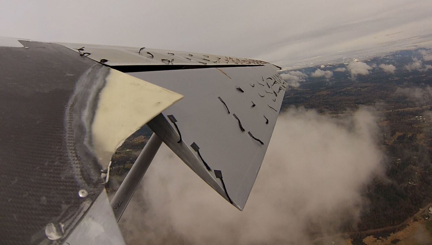
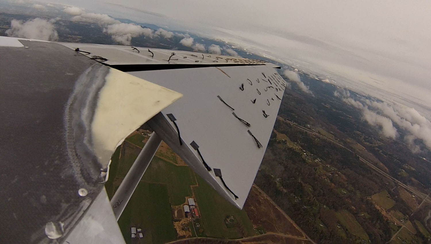
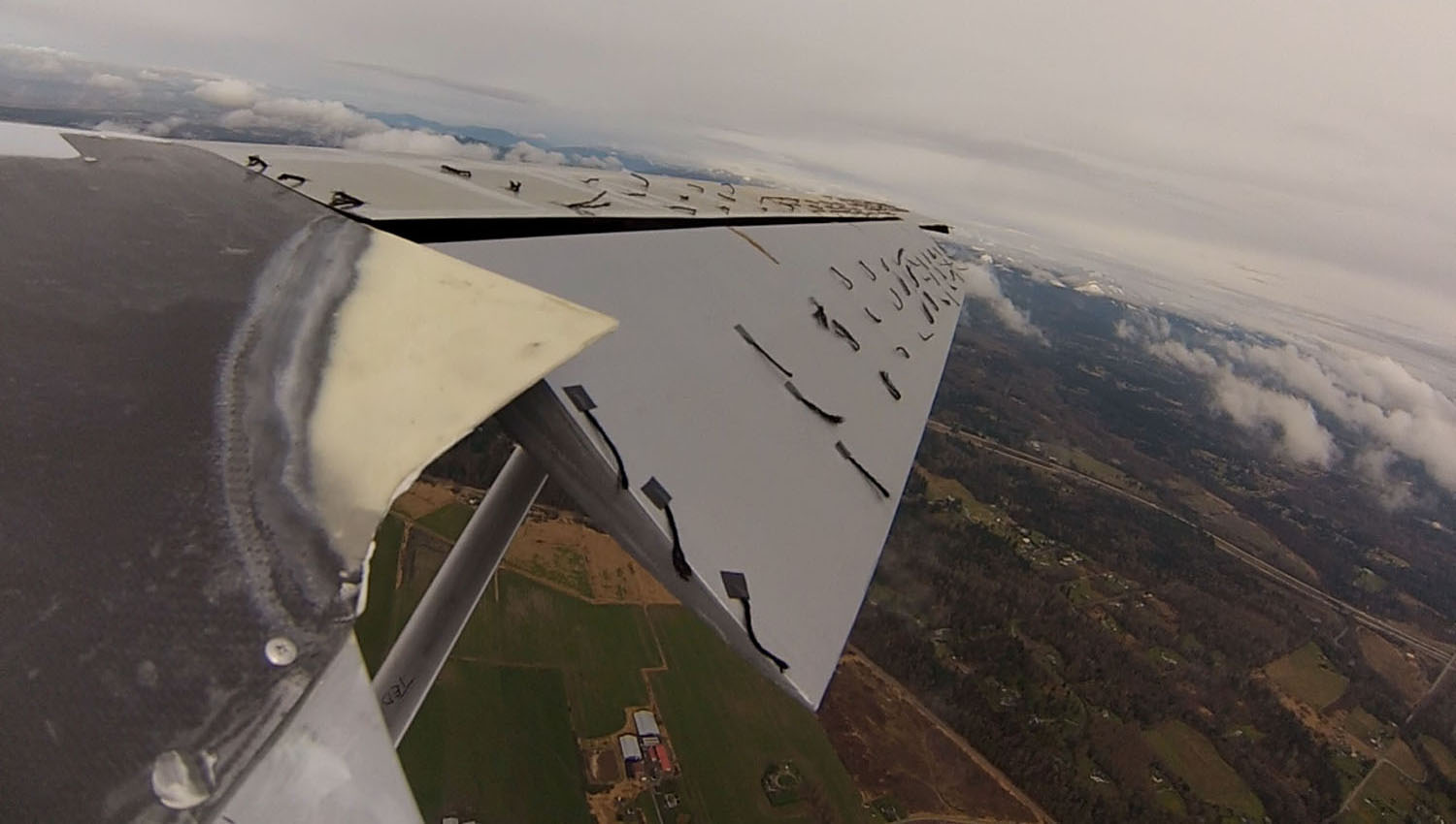
The video clip shows the right wing and flap as it enters a stall at the 35 degree position. Prior to the stall you can observe that some of the tufts on the flap are “active”. They aren’t stalled, but are immediately behind the flap tracks and flap pushrod in disturbed airflow. This is a bit misleading. We should have done a better job of positioning them in clean sections of the flap coves. You can also observe the inboard tufts on the wing stall first and if you look closely at the outboard section of the wing, you can see the tufts behind the delta wing vortex generator are still trailing nicely indicating the wing is still flying out there. When the airflow stays attached outboard, it means that you retain aileron control as well.
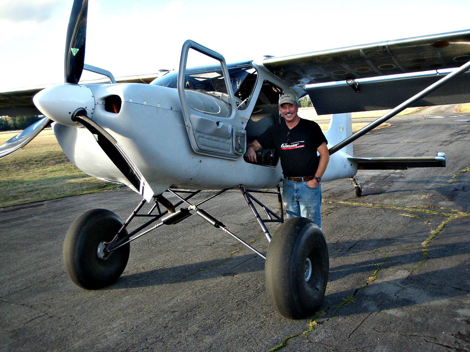
Flying the “Setzman”
By Alan Negrin
After spending countless hours helping Ted Setzer (he actually kept track of them) build his “Super” Sportsman, I have been honored with an opportunity to fly it several times.
Ted asked for my impressions of it compared to a stock Sportsman.
I think Ted achieved and possibly exceeded his goals. I am very impressed with the airplane. Empty weight before paint is roughly 200 lb lighter than most Two Weeks to Taxi Sportsman, and it’s noticeable immediately.
Modifications on the aileron bell cranks and the flaps add even more amazing characteristics. The roll rate is phenomenal and the slow flight, stall, and landing speeds are dramatically improved.
The usual power-off stall speed of a stock Sportsman is 42 knots. Ted’s is at about 37 kt. The power-on stall speed for the typical Sportsman is about 33 to 35 kt indicated, but Ted’s is down around 30 or maybe even less. Of course with the extremely nose-high pitch attitude, the position error of the pitot tube must be extreme, but you know you are going darn slow before there is any kind of shudder and break in the stall.
The biggest and most amazing effect that I experienced was on landing. The slowest I have been able to get any other Sportsman to fly and still have reasonable control in a short field landing is about 52 kt. I was consistently landing Ted’s Sportsman at 42 kt and felt like I had lots of control. The last flight test I did was with six-inch tires. I am sure that it can go even slower with the large tundra gear and bush wheels. Ted has matched and probably exceeded any Aviat Husky for take off and landing performance. And if he has not matched the Carbon Cub numbers, he is very close.


