This modification to the fuel system is different from the stock fuel system design, so be absolutely certain you know what you are doing and test extensively if you modify the fuel system of any aircraft. Remember that you are responsible for the safety and airworthiness of your aircraft.
It has been a good week also: in addition to getting the top deck put on, I tested the definitive version of my fuel system.
I filled the tanks with water and folded the wings back. Only 10-15 cc of water came out the vent tips. Water flow in level attitude was 35 GPH and 26 GPH with the plane on its tail wheel. With a Facet fuel boost pump (cube type) in series with the gascolator the flow dropped only to 29 GPH level and 21 with the tail down. So, the Facet boost pump offers no significant resistance to fuel flow.
 Once gravity flow stopped that meant I was down to the header tank (4 gallon job sitting behind the pilot seat on the floor) so with the airplane on its tail and I energized the electrically driven pump provided with the fuel injection system built by CrossFlow as part of my 180HP engine package. It sucked the header dry except for the 8 oz available only to the sump and did not lose its prime when I turned it off for a few seconds at a time. The elevation difference between the pump and the tank is about 16″. That means (I think) that most of the capacity of the header may be usable such that my total usable fuel (with aux tanks) is about 53 gallons.
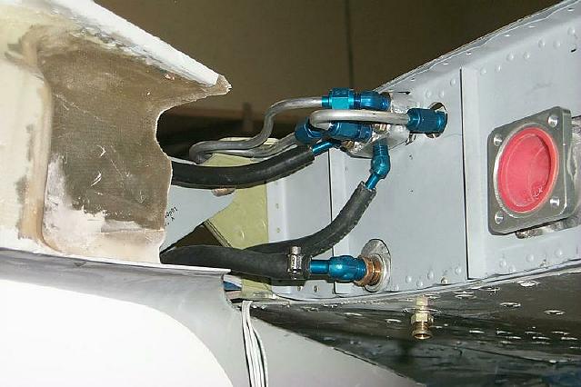
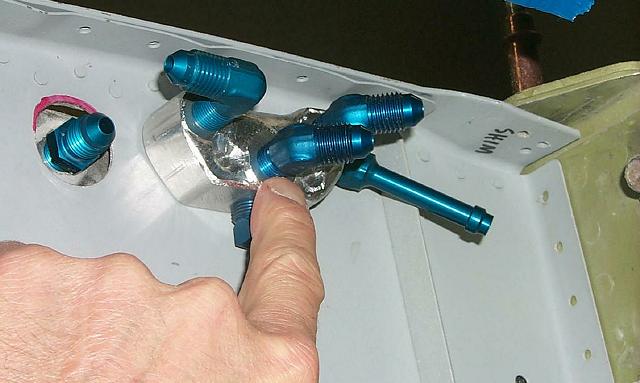
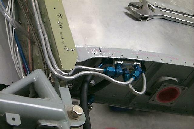
My tank vent system is different than S-H plans. There are 5-port manifolds bolted to each wing root rib just forward of the aft spar. The outboard port of each main tank comes around the aft spar and forward to the manifold. A line runs outboard from each manifold to the wingtip. Another port goes to the fuel return boss on the inboard side of each main tank, There is a crossover tube and on the left a vapor return line from the header to the manifold. Occluding one or the other vent tip did not affect the fuel flow. I used 1/8″ aluminum line for the vents except for 1/4 flex hose for the crossover and wingfold flex parts and the 5/16″ line for the fuel feeds. The inboard parts of this plumbing is below water level when the tanks are full but it does not present a problem with sucking air bubbles into the tank for venting. The inboard fuel return port is what breaks the siphon when the wing is folded down.
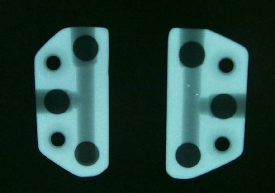
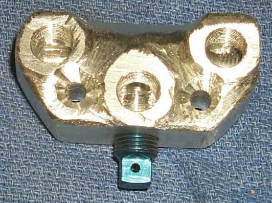 The photos show the plumbing and an x-ray of the manifold. It doesn’t show too well in the picture, but I had to modify the wing root fairing to accommodate all the plumbing. However, all the fittings are outside of the cabin and a leak there should drain outboard.