Want a unique pitot tube? Follow these instructions from Eric Jones and build a custom heated pitot tube. Eric Jones can be reached via his website www.periheliondesign.com.
Having bought my GlaStar kit from the previous builder, the pitot tube I got was not heated, and I wanted a heated pitot tube for flying in the Northeast.
Pitot tubes are the about same size and do the same thing on big airplanes and little airplanes, fast or slow, and they all draw 10 to 20 amps from the electrical system. One of the reasons they are such power hogs is that they are made of metal, which conducts the heat away rapidly. Pitot tubes are 1930s designs, and I believed I could update this design.
I reasoned that a pitot tube should have a number of characteristics:
- It should draw no more current than necessary to do the job. (It should be thermostatic.)
- It should pretty much take care of itself, that is, it should remember to turn itself on and off. (It should be automatic.)
- It should be built of a low thermal-conductivity strong stuff. (It should be fiberglass.)
- It should be low drag. On a regular pitot tube, the perpendicular part of the L-shaped tube exerts a drag about equal to half-a-foot of wing strut. It all adds up. Likewise the junction with the wing must be faired too. (It should be aerodynamic.)
- It should protect itself against mud wasps and various bugs attracted to its hole. (But I never figured out a slick way to do this.)
- It should be rugged.
- It should work well enough. (Perfection is not required. All pitot tubes have calibration errors. A perfect airspeed indicator shouldn’t be done with a pitot tube at all.)
- It should be beautiful.
Some other considerations:
- The FAA wants an orange instrument panel light to show when the pitot tube heater is on. Well, this one is never really off, so I don’t yet know what to do about this; but an LED which shows that the pitot tube is drawing over for example, one amp, is easy. As they say, the exercise is left for the reader.
- There is a lot written on pitot tubes so a key question is whether or not this thing functions like a real pitot tube. I set up a differential U-tube manometer and connected one hose end to the original SHAI pitot tube and one hose end to my new design. Although I didn’t have a calibrated airspeed source (or indicator….or airplane!), squirting a compressed air hose a couple feet away at both tubes did not seem to show any differential pressure between them. That’s close enough so that mounting it on the aircraft seemed a reasonable thing to do.
Thermistor characteristic
I looked into the electronic means of doing this, including PICs and some clever chips and finally settled on PTC (Positive Temperature-Coefficient) thermistors. These are used, for example, to defrost automobile rear-view mirrors. They are rugged and seemed made for the task. They have a characteristic low resistance which increases sharply above a specified transition temperature. So they could be 50 ohms at 25 degC and 1000 ohms at 35 degC. Thus they would try to maintain themselves near their transition temperature. I calculated that six of these in parallel would generate about 20W.
I spoke to the manufacturer and they agreed that the parts would do what I wanted. The shapes of thermistors are limited unless custom parts are designed. I did not have a need for tens of thousands of these, so Digikey supplied a dozen KC001P for about $20. Not an ideal shape, but they would do.
I tested these and was certain they would work. In very cold water, the thermistors made a valiant attempt to boil the water, yet they were only slightly warm to the touch.
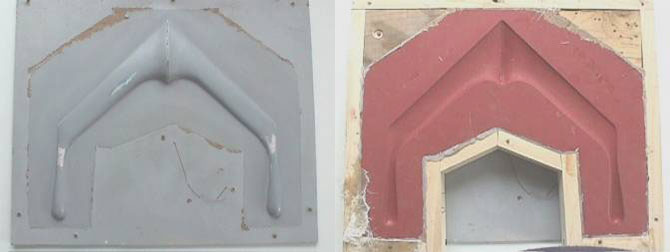
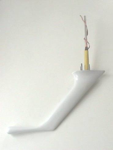
I carved the streamlined boom form out of white pine and spackling and was satisfied with the result. I decided to build the boom out of fiberglass in silicone rubber molds. This is not the cheap way to do it but I had some spare silicone rubber, so I used it. Add the cost of two sweaters and a pair of jeans with red silicone stains, however. But it allowed me to make more if I wanted.
When the mold was finished, I waxed it and mixed up a gel coat and applied it. When it was just tacky I laid in a layer of fiberglass and soaked it with more resin. (By the way 3/4 the difference between a fiberglass expert and an amateur is basically how many hours one is willing to commit to sanding and filling and sanding and filling to achieve the required form. There are some tricks, but they would fill only a 3 x 5 card. The real trick is patience and commitment.)
I made the inside of this pitot tube with 1/4” aluminum tube bent to match the streamlined shape. The aluminum tube is not the best or most reliable electrical conductor, so I wrapped the tube in adhesive copper foil. I removed the leads from the PTC thermistors with a soldering iron. The faces of the PTC “pellets” were then soldered on, corncob fashion, to the nose end of the pitot tube. Breaking the pellets into D-shaped parts would have made placement easier and would have done no harm to the PTC.

When one side of all these parts was soldered to the copper foil covered pitot tube nose, I wrapped a piece of braided copper shield around it to make contact to the back side of the PTCs. This wire was carried up to inside the wing. The other terminal was the copper foil tape and aluminum tube.
Before everything was buttoned-up, I checked that the resistance across the terminals was 11-14 ohms at room temperature. When the basic device was checked and working, I dipped the heater assembly into some silicone sealer, and when that dried, I wrapped the heater assembly in a little silicone tape to secure the wiring, and then added mounting studs for fastening it to the wing.
I then took the two roughly-trimmed halves of the streamlined shell and stuck this all together with a prepared resin/glass micro-balloon milkshake. I wrapped the assembly in kitchen plastic wrap and waited for it to harden. I then sanded and sealed and primed and painted it GM 387 to make it look like a real GlaStar part.
If the device at room temperature is connected to 12 volts, the current through it is small. Nothing much appears to happen! But with the pitot tube in the freezer the current increases by 15X or so. Upon removal from the freezer, the nose is warm and the current soon returns to normal.
But I haven’t flown with the thing yet. My GlaStar #5540 is still about a year from takeoff. But from the sleek looks of the pitot tube it should be very fast.


Well.. it’s been eleven years. Seems to be enough time to get that sleek looking pitot tube flying. I’d love an update on this!