Heated pitot drain: I installed the system per the plans. The drain valve in a push-to-drain device. It is mounted just below the left-rear of the pilot’s seat location, just forward of the cross tube. After I located mine, and drilled the hole, one of my knowledgeable hangar partners suggested that I should have rerouted the pitot line inside the cockpit to run forward above the door rather than under the seat. That way I could have mounted the drain behind the instrument panel the way it is in some factory-built planes. I then could drain the system into a cup while sitting inside the airplane, or even in flight, and I would have have had the extra hole in the fuselage shell. I always receive such ideas just after drilling the holes.
I don’t remember about the FARs, but I do know that it’s an air safety issue. Put the drain in. Every well-thought-out schematic I’ve ever seen of a pitot system showed a drain. But I’ve never done an inventory to see if everyone has one.
–Joe Colquitt
Icing-tolerant pitot tube: This pitot tube system was patterned after one used on some vintage gliders when cloud flying was legal and encouraged. It served quite well for the small amounts of icing formed during short duration in clouds. It also inhibits impact water from entering the pitot line where it could freeze and affect the airspeed reading.
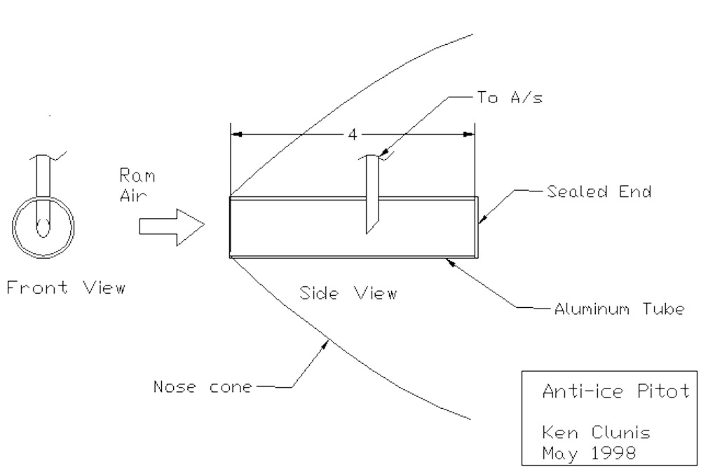 In theory, any ice which might form would coat the exposed surfaces gradually building up a thick layer. By making the entry relatively large (about 1″ diameter), it will take quite a bit of ice to cover over it. Any water that enters the main tube may impinge on the forward side of the pick-off tube where it too might freeze. By having the open end of the pick-off tube facing to the rear, the possibility of ice covering the opening is reduced.
This is not a system intended for serious IFR as a replacement for a heated pitot tube. Rather it is a system which is superior to a straight pitot in many respects and yet is easy to construct. The dimensions are not critical.
A one inch diameter aluminum tube forms the main part. The pick-off tube can be either 3/16″ or 1/4″. The main tube must be sealed at the end with a cap of some sort and the pick-off tube must be glued to the main tube. I had mine welded, but I think that silicone sealer would work just as well.
Since I built mine in from scratch, I can’t offer a method for retrofitting one.
–Ken Clunis
Pitot tube installation: Today I looked again at the left wing (before any close up) and decided to add four little nutplates on the inside of the pitot tube mounting plate. For the little extra effort, it sure will be nice not having to try and put my big hand in that little hole and hold a wrench on those washers and nuts.The four nutplates can be installed on a small piece of alum. and the assembly placed over the installed plate and secured with just tow additional rivets. The four machine screws do the real holding.
–Jim Rose


