Submitted by Bill Wilson, GlaStar
I developed a servo-driven electric rudder trim and installed in the GlaStar kit I started in August 1996. I won’t know the true success or value of the device until I get airborne, but I knew I didn’t want to do the bent-tab adjustment process for rudder trim.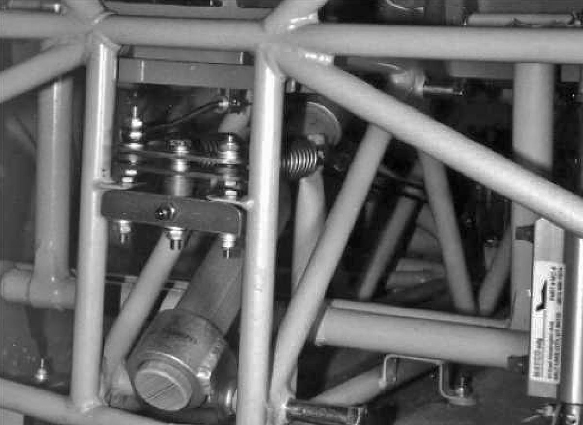
Rather than attaching the rudder springs to the tabs provided on the cage at the firewall, I mounted a horizontal aluminum block between those tabs (after removing the vertical ears), which supports a horizontal pivot arm to which the springs are attached through 4130 steel links longitudinally in line with the rudder cables, springs and cage tabs. One link is longer than the other such that the springs are at equal tension at neutral rudder.
The bolt carrying the right spring link through the pivot arm is longer and extends upward through the eye of a 3/16″ rod-end bearing, and all three pivot points are locked up for rigidity with appropriate spacers and Nylock nuts. The actual rotating points are bushed with Oilite bearing stock.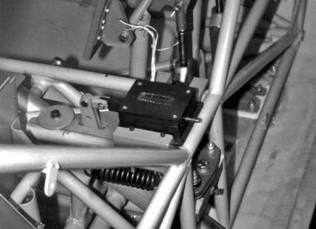
Bias on the springs to achieve trim is provided by a MAC 8A 12volt DC servo-motor acting through a vertical pivot bar linked with a pushrod to the rod-end bearing at the right-side spring attach point. Travel is limited by stop pins in the block supporting the pivot arm, and 1.3:1 leverage is provided in the spacing of the linkage holes from the central pivot hole.
The vertical pivot arm support block is captured between the cage tubes by an aluminum plate under the tubes bolted through the block to the servo mounting plate. This forms a rigid structure for mounting the linkage and the servo, which was slid into milled slots and secured with hex-head machine screws to prevent fore and aft slippage. The entire assembly does not interfere with the tricycle nose gear leg.
A primary consideration was to place sufficient tension on the springs at neutral, such that there remained positive tension on both springs with full rudder override. Without positive tension, there would be risk of the spring releasing from its linkage. To achieve this goal, it was necessary to mount the pivot in the forward plane of the cage, which means a “pie-plate” will have to be made in the firewall to allow full pivot without interference.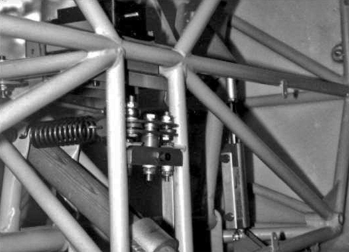
The upside is that this plate allows inspection and service access.
Materials and hardware were available through Aircraft Spruce and Specialty except for a few pieces of 6061 aluminum I had on hand.
Hardware is AN, spring linkages are fabricated from 4130 steel, and the horizontal and vertical pivot arms were constructed from dual pieces of .090 6061 left over from wing spar materials.
Cost was nominal, but development and construction took about seventy hours, most of which were creatively enjoyable.


