One of the biggest challenges for GlaStar builders arises in the “home stretch” of the project. This challenge is affectionately referred to around our shop as “the frigging rigging.” Here, Cal explores some aspects of rigging the ailerons.
The greatest number of rigging difficulties we have encountered on the GlaStar are in the aileron system, and that is what I will address here.
The aileron cables and bellcranks should be installed per the manual without too much trouble. However the control stick interconnect rod has caused some heartburn. The common difficulty builders have encountered is having too much total travel. The interconnect rod should be adjusted to be as short as possible. Even then, however, early kits have an interconnect rod that is too long to allow the builder to limit the total travel of the ailerons to the specified 22.5° up and 17.5° down travel using the elevator/aileron control yoke per the manual.
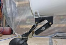
If this is the case with your kit, the best solution is to install simple stop blocks between the control yoke pivot arms and the control stick pivot brackets at the location indicated by the bold arrow in the figure. These can be as simple as what we used on our prototype, which were Nylon cable ties wrapped around the pivot arms, or as elaborate as welding a threaded insert into the pivot bracket and using a fully threaded bolt and stop nut.
Another option that has been used successfully is to fasten a piece of UHMW polyethylene or equivalent onto the pivot arm and trim it until you get the desired travel.
Having said all of that, let’s get back to the job at hand—rigging the ailerons. With the wing complete and installed per the manual, check first to see if the aileron bellcranks are perpendicular to the aft spar when the interconnect rod is centered within the control yoke. If not, adjust the power and balance cables to achieve this.
Then you can preliminarily fair the ailerons to 1/4″-1/2″ below the wingtip fairings by adjusting the pushrod at the aileron. (You will need to establish a repeatable neutral position either by sight lines or measurement of the pivot brackets or interconnect rod.) Check the travel for each aileron from this neutral position. You should be close to the figures given above. Adjust your stops as necessary to get the 40° of total travel. To get more up and less down, loosen the crossover cable one turn and tighten both power cables half a turn; to get the opposite, do the opposite.
You may find that you need to enlarge the pushrod slot in the spar web slightly at the inboard end, but do not grind into the aileron hinge rib web. If more clearance is needed, remove the spacers on the aileron pushrod attach bolt and retrim them to provide clearance to the aileron hinge rib.
Once you have established the correct up and down travel, it’s time to set the final tension of the cables and the fair of the ailerons. The cables should be tensioned to about 20-25 pounds, but the real setting should be one that allows the stick to return to neutral after you have deflected it to one side.
If you need to loosen the cables, start by loosening the balance cable one turn, followed by the power cables half a turn each.
This is all you should need. The ailerons should be set so they are about half an inch below the tips when on the ground, because they will fly up about an inch from there in the air.
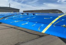
If your flight test reveals a heavy wing, there are several things to look for: are the wing angles of incidence equal? Are the flaps tucked up the same on each side? Is the gap in the aileron cove the same on each side? Does the wing skin “ski jump” at the back of the aileron or flap cove more on one side than the other (i.e., does the trailing edge turn up slightly ahead of the aileron)?
Ways to cure a heavy wing would be to change the incidence per Service Bulletin 25 or by installing a trim tab (a 2″ x 9″ piece of .032 is about right) in the middle of one or both aileron trailing edges. One builder has reported having success by just bending the trailing edges of the aileron up or down appropriately with a hand seamer. One could affect a heavy wing by changing the gap or “ski jump” of an aileron cove.


Sorry my last comment incorrectly named the pulley blocks I am concerned with.
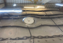
I should have indicated that the Outboard Aileron pair of pulleys appears to inaccessible without an additional access panel in the lower skin.
Service Bulletin 48 part 2 identifies the ‘two aileron pulleys just inboard of the ailerons’ ; continuing with cove skin panel access drawings for the inboard pair of aileron pulleys, but no drawing of an access panel for the outboard pair.
The access panel for the flap pair in the cove skin is elsewhere of course.
Can you please provide some advice concerning access to the outer pair?