This builder tip was submitted by David Walker, Glasair II-S RG.
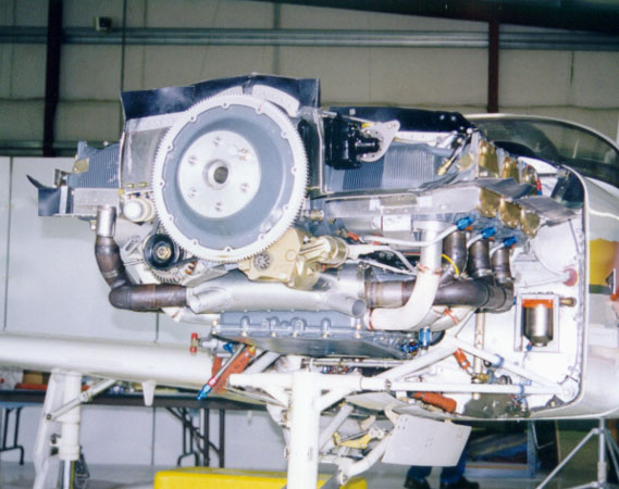 Coming to the point where you want to align your engine to the firewall? The method in the manual-parallel fit the cowling to the sides of the fuselage and align the engine to the cowling-is an unspeakable insult to all the fine work you have done up to this point and makes immoral assumptions over the accuracy of the cowling molds. Setting up engine mount alignment according to the cowling?! No way! This is putting the cart before the horse.
The difficulty is that the centerline of the aircraft and the (offset) centerline of the engine cross at some point forward of the flange. But where should they cross? At the center of the propeller thrust plane — and that’s dependent on the propeller design and a point somewhere out in space forward of the engine flange!! But where?
So what did I do? (And this is great for the subsequent accurate alignment of the cowling.)
Preparation
1. Call up your chosen propeller manufacturer and ask for a cross-sectional drawing of your propeller. You need this to determine where the thrust line is (i.e., the plane of the propeller blades). You have to make your propeller purchase decision at this point as all propellers are different. (I can recommend MT three-blade props as used by Henri Chorosz, Hans Gutmann and Jorg Sommeraner on their long-distance flights.)
2. Have a friendly woodworking shop machine you a piece of hardwood. The diameter is the opening in the cowling, and the length is the distance from the flange to the propeller thrust plane as supplied by manufacturer. The lathe markings, incidentally, automatically give you the center point of the axis, and this is the point for all subsequent activities. Have the woodworker drill the holes for the prop bolts in the block; don’t forget to machine a hole recess for the variable-pitch boss (see flange for dimension) or the block won’t fit flat on the propeller flange.
3. Level up your aircraft accurately with a water level, using the wings if possible, tailplane if not (the wing gives more accuracy) in both axes.
4. Mark the exact middle point between the wing attach fixtures as a reference. If the wing is not attached, then drill two holes to match exactly the distance between the wing attach fixtures and install an aluminum bar between the wing attach fixtures inside the fuselage (and then stare in disbelief at how much you have to push in/out the sides of the fuselage to get it installed! The bar is useful later to hold the fuselage sides in place while doing critical installations like the windshield.)
Doing it
1. Lateral engine alignment
Run a nylon fishing line from the center of the fin to some kind of fixture about 7 feet off the ground-we used a plastic electrical conduit across the wall of the workshop. Make sure the line is under tension. Move the nylon line along the conduit until a plumb bob points to the center wing marking (see preparation steps above). The fishing line can now be used as the extended center line of the aircraft. Don’t ever lose this point!
Using a plumb bob, move it along the fishing line until the bob line lies across the face of the wooden fitting. Using aluminum shims with a cutout to the center hole for ease of installation, insert behind the upper engine mounts until the plumb bob hanging from the line hits exactly the centerpoint of the wooden fixture as machined above. You now have simulated exactly the thrust line of the propeller in the lateral direction, and the engine centerline crosses the axis of the aircraft at exactly the right point forward of the flange.
2. Vertical alignment
Using a water level between the WLlOO markings on the tail, insert aluminum shims until the vertical alignment is OK. The lathe marking on the center of the wooden fixture is the point.
Steps 1 and 2 may have to be repeated a couple of times until everything fits, as they mutually influence each other.
Finally, measure the combined thickness of the shims used to align the mounts and note this pending final installation, when you will install washers to this thickness.
And what do you do with the wooden fixture? Use it for your next barbecue, or better yet, use it to fit up the cowling to a level of accuracy never dreamed of in Arlington. Again you need to know the depth of the spinner from the engine flange or propeller thrust plane and the dimensions of the selected spinner (call the manufacturer). Mark this point on the wooden fitting (remembering to leave adequate spinner-to-cowling clearance!) and adjust the firewall edges of the cowling accordingly.
You cannot align the cowling and engine more accurately!
And while I am in S-H-criticizing mode, don’t use the S-H method of longitudinal joining of the cowling! (It’s OK for the vertical.) The curve of the cowling means that it is most difficult to join the two piano hinge halves without a power screwdriver to drive in the hinge pin! You are on a foreign field, it’s raining, and you need to take the cowling down: where’s the power driver? Do yourself a favor and use standard cowling fittings instead and sacrifice 0.1 knots.


