This tip was submitted by Troy Scott, Glasair Super II RG.
Shortly after I began construction of the slotted flaps for my Super II, it became apparent that I needed a better way to assure that the finished flaps would be aerodynamically well matched to my wing. I was unhappy with the results I was getting by trying to move the panels inboard and outboard to find a good fit. After talking with Lanny Rundle, John Kerner and Fred Van Raden, I decided to just center the foam cores between the ribs and alter the flap thickness by adjusting the spar height, letting the leading edge overlap vary as necessary.
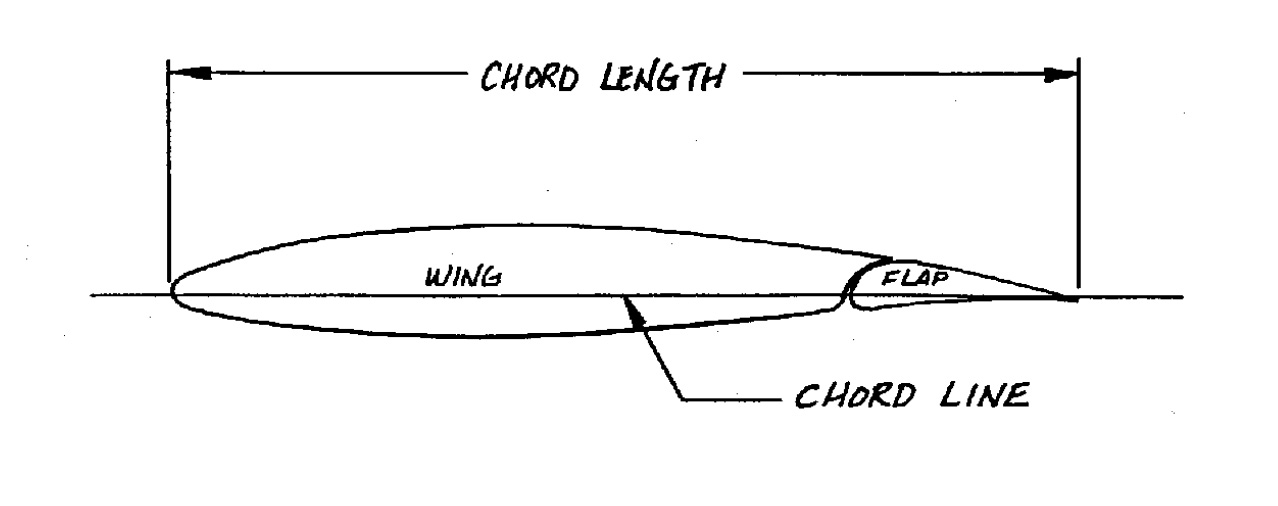
Obviously, the flap thickness could vary considerably, since we will be building a “wing upper trailing edge extension and flap slot” (hereafter referred to as “bridge and slot”) to “blend” the wing airfoil into the flap airfoil. My objective was to find a flap shape such that, for any chordwise location, the aft several inches of the upper wing skin forward of where the bridge will be, the bridge itself, and the aft several inches of the upper flap panel are all part of the same aerodynamic curve, like the idealized version in Figure (G-3) of the Instructions.

We are given several fixed parameters:
- The location of the lower flap skin;
- The vertical center of the flap trailing edge (on the chord line);
- The chordwise location of the trailing edge of the bridge, which should overlap the leading edge of the fully deployed flap by 1% of the total chord at any chordwise location; and;
- The chordwise location of the trailing edge of the flap.
The variables are:
- The thickness of the flap, (controlled by the height of the spar);
- The thickness of the trailing edge of the flap;
- The thickness of the trailing edge of the bridge;
- The size of the slot when the flap is retracted; and
- How far forward or aft the upper flap panel is positioned relative to the lower panel.
Using Fred Van Raden’s trailing edge board technique (described in an earlier newsletter), the location of the lower panel is easy to determine. Just let the lower panel rest on the angle Clecoed to the lower trailing edge of the wing, and on the trailing edge board. Note that the trailing edge board should be lower than the chord line by one half of whatever arbitrary thickness you choose for the trailing edge. I am making my trailing edges 1/8″ thick, so my entire trailing edge board is 1/16″ below the chordline at any chordwise location. The lower panel should now be indexed to the jig, and the lower panel should be trimmed to match the trailing edge board. The trailing edge of the upper skin doesn’t need to be trimmed until after closure.
 The chordwise location of the trailing edge of the bridge is easily determined. Just go ahead and mount the ribs and all the hinges, and rotate the lower flap panel alone to maximum extension (40º in the Super II). Then use a plumb bob from several locations on the leading edge of the lower panel to create a line on the floor representing the leading edge of the extended flap. In a similar manner, create lines on the floor representing the leading edge of the wing and the trailing edge of the flap. Also draw some lines on the floor parallel to the longitudinal axis of the airplane and under the wing/flap.
Now measure the total chord at several stations and create a line exactly 1% of the total chord aft of the extended flaps leading edge line. This line represents the trailing edge of the bridge (see Goals of the Flap Installation Procedures, Item 7, in the Instructions). Using the plumb bob, this line can be transferred to the level of the upper skin of the flap. The line should be drawn on the upper panel of the flap. There should be a small amount of chordwise curve in the upper skin aft of this line. If not, you may want to erase the line, move the upper panel, and redraw the line.
Once you are satisfied, the upper panel needs to be indexed to the lower panel. Now, make a feeler gage equal to the sum of the thicknesses of the trailing edge of the bridge and the size of the slot when the flap is retracted. The instructions suggest four layers of duct tape to predetermine the size of the slot with the flap retracted, which would be about .040″. I chose .060″ for the thickness of the trailing edge of the bridge, so my feeler gage is 1/10″ thick.
Next you need a flexible straightedge, like the popular 48″ aluminum rules found at better hardware stores. Use the straightedge on the flat so that it bends under its own weight. Place it chordwise over the wing/flap with the 24″ mark centered over the gap. The flexible straightedge will be tangent to the upper wing skin three or four inches forward of the gap, and to the upper flap skin a few inches aft of the bridge trailing edge line. Adjust the height of the spar so the feeler gage will just fit between the 48″ rule and the upper flap skin directly over the line representing the bridge trailing edge. The underside of the flexible straightedge represents the top of the bridge.
Regarding Fred’s trailing edge board addition to the wing jig, I made mine all one piece and indexed it to the wing in such a way that it is easy to remove and replace as necessary for convenience in building. I screwed a piece of 1″ x 1″ x 1/8″ aluminum angle to the aft upper edge of the trailing edge board so that the aft edge of the angle is actually the trailing edge. This has made closing the extended tips, ailerons and flaps very easy and precise. I just place another piece of angle on the top panel directly over the trailing edge angle, and use common clothespins, about every two inches or as necessary.