- Version
- Downloads 211
- File Size 1.83 MB
- File Count 1
- Create Date January 12, 2017
- Last Updated January 12, 2017
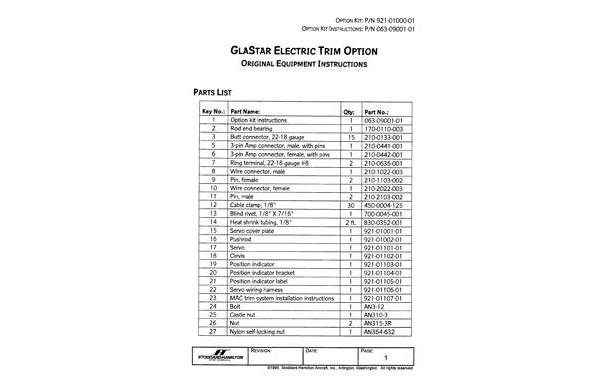
ELECTRIC TRIM OPTION
The electric trim system consists of an elevator-mounted servo, which controls the position of the trim tab via a rigid pushrod linkage inside the elevator structure.
The instructions are divided into the following sections:
Advertisement
- Basic Servo Installation: making the servo cutout in the elevator skins and ribs.
- Pushrod Installation: installing the pushrod linkage from the servo to the trim tab control horn.
- Final Servo Installation: mounting the servo in its cutout.
- Wiring Installation: installing the wiring harness from the cockpit to the tail, as well as related electrical components.
- Cockpit Installation: installing the control switch, trim tab position indicator and related components.
- System Adjustment and Final Assembly: adjusting the pushrod linkage and sealing the servo cover.
Attached Files
| File | |
|---|---|
| 063-09001-01-GlaStar-Electric-Trim-Instructions-1.pdf |