 For those of you using the tail wheel option, having just attempted to fit this, be aware that the instructions in the manual, Steps 90 onwards, Section IX are in error and do not work. Until they are rewritten, exercise caution if you undertake these steps. The problem is that the shape of the fuselage does NOT allow you to fix the springs approximately parallel to the waterline, as called for in the construction of the Forward Spring Block (see Figure 152, p 267). I found this gave a gap far greater than the aft spring attach brackets could accommodate. The option would just not fit.
I suggest the following areas of cautious attack:
Advertisement
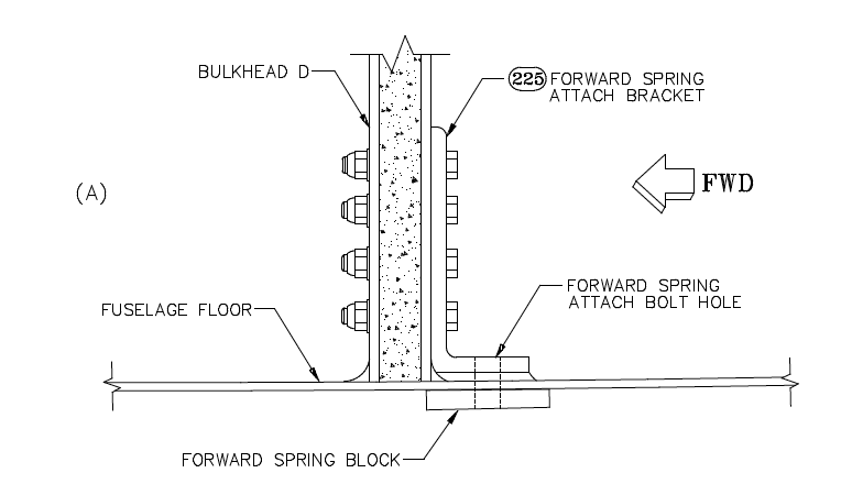
- Step 92. Be very careful when drilling the 3/8″ hole as called for. The close presence of the bulkhead means that the awkwardness of getting a drill through the bracket predisposes it to being sloping forward if anything (unless you are lucky enough to have a 3/8″ drill to fit your angle drill) whereas if anything the hole should slope rearwards. Note that to fit, the springs will slope upwards relative to the waterline, whereas the hole in the bracket is at right angles to the waterline (because the bulkhead is!) Check “fit’ the springs before you drill the hole to see what the angle is with the springs stacked together. Maybe a coarse rasp to finish of an undersize hole may be a better approach than a wrongly angled drilled hole.
- Step 93. Check fit the springs to lie just clear of the underside of the fuselage with LESS than a 1/2″ gap (the INITIAL! thickness of the aft block BEFORE shaping) at the aft joggle. Your front block will need to have a shape to leave the bottom surface parallel to the line of the top of the spring set in this position. The shaping set out in the manual is WRONG and results in the bottom level being nearer the level of the waterline which means a big gap if not reshaped. I have yet to reshape my block shaped as per the figure, but I suspect reversing it to the measurements given in Figure 152 (ie making the FWD arrow AFT) may be nearer the mark – I hope so! Do drill the centre hole at right angles to the bottom surface as instructed, as if fitted as above this will be the correct alignment.
- Step 96 should proceed as written provided the forward block is made as above. Note however that the AN4-20A bolt called for in Figure 157 is too short by 3 dashes and a longer bolt than supplied is needed Step 97 should proceed as written, again provided the clearance is kept below 1/2″ in step 93 above.
–Peter Washbourn


