I have been interested in making some changes to the MAC8A Elevator Trim Servo since I first got Glastar kit #5540. I thought the servo was a bit “model airplane” quality, and the failure of the servo mechanism (no servo or runaway servo) could be a big problem. Some improvements are easy to make.
I also surmised that the stick with push-button switches, a hat switch, or a toggle switch with spring return, all necessitated a visual indicator to show what the trim was doing. This seemed inelegant and although it seems simple, the trim is used quite a lot.
I began to see that a Pulse-Width-Modulated (PWM) servo allowed one to have much better control over the trim position and did not necessitate looking at the bar graph display.
A control knob position (a potentiometer with a knob in the joystick control grip) would stay in sync with the servo position, thus allowing tactile feedback to the pilot’s hand and brain automatically. Of course the knob would be one that would be easy to feel the position. They cannot get out of sync either. By the philosophy of “less is more,” I decided to do without the visual bar graph display entirely. With a custom tactile position setting lever on the joystick control grip, to trim nose-down; you rotate the lever forward and down; to trim nose up, you rotate the lever rearward and down.
Neutral trim is straight up. (Alternate schemes are simple.) This is sort of a “little stick on the big stick”. I would have one only on the left stick, as is customary. I would also arrange to have the control grip demountable via an “Amphenol” connection (as is done on military aircraft). This simplifies servicing and modifications.
Beefing up the MAC controller
The MAC controller has a couple of possibilities for improvement:
- Cover the actuator screw: This takes a part which could be made from a ball-point pen cap or any other minor piece of plastic (or aluminum) glued onto case to cover the screw, which extends 1-1/8 inches out from the housing. This seals one of several possible entries for dirt, water and corrosion. It is axiomatic that excluding dirt from a mechanism such as the servo is a very good way to extend its life.
- Cover the actuator square rod: A small extensible boot can be fashioned to cover this part. Otherwise a wiper made from Goretex, little brushes, etc., could be made for it. Same reason.
- Seal the cover: A little (very little) non-hardening gasket seal. Tape on the seam would technically be better because no sealant could get into the parts.
- Run the cover screws through the body: This is a minor point; but some improvement can be made by using metal inserts in the case. Unfortunately plastic threads also supply some degree of locking for the threads, so replacement may be made later.
- Connectors: Really decent cheap connectors can improve the “auto” connectors supplied with the kit. Instead of putting a connector on the rear bulkhead, consider putting a socket on the servo cover with only the cord running through the rear bulkhead. This would eliminate some weak points in the design.
Changes to the inside…? Well, I pored over this and believe the inside is actually pretty good. There is no way to know how tough the plastic parts are, but there is good reason to believe they are fine. Time will tell. But it’s on the annual inspection list for sure.
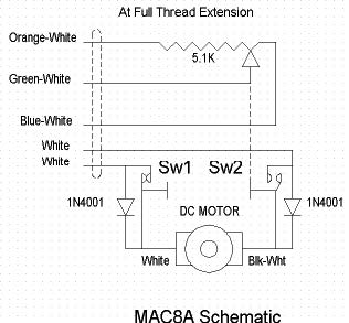
The servo is shown at the position where the brass actuator thread is fully extended (the square rod is fully retracted). The limit switch SW2 has opened, allowing ONLY movement in the opposite direction. The 1N4001 diode conducts only until the limit switch SW2 again closes (almost immediately). The motor can drive the rod all the way to the other end so that the other switch SW1 opens, or the motor can stop anywhere in between. Electronic types may see that sprinkling around a few 0.1 uF caps might be a good idea.
There does not seem to be any EMI capacitor on the motor (it may be inside the motor but otherwise it should be well filtered), and that the linear potentiometer merely supplies leads to the outside. Ultimately these are used as a voltage divider with the voltage displayed by the bar graph display.
I looked into IC’s that might ease the design difficulties.
Many of the parts that would do the job actually demand a microprocessor input—since now almost everything does— and it would provide some neat features. For me, and for now, I would like a microprocessor-less design.
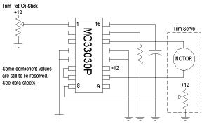
ST-microelectronics makes some neat parts for this task, but Motorola /On Semiconductor makes the absolutely perfect part called a DC Servo motor Controller/Driver MC33030.
This device allows connecting the existing servo potentiometer for feedback and putting the aforementioned potentiometer on the control grip (the potentiometer values don’t matter much, 100? or 1K? will do but the slope probably should be linear). Running a wire back from the stick to the servo controller is simple. The load current should be watched. The MC33030 is good for one amp. A little EMI control would be advisable, but it all would depend on details of installation.
The wiring of the MC33030 is so simple that I would consider not using a real PCB at all, just a little scrap of perfboard.
That the only thing happening here is that the potentiometer in the control stick grip is a voltage divider. The potentiometer could be one of the new hall effect pots that last forever, or it could have a tie in to an automatic control circuit that would present a voltage that is proportional to some quantity. So it’s very easy to make this work in other ways.
An additional advantage of this system is that if the control circuitry is left in the tail, only ONE wire and maybe ground needs to be sent back to the tail. That’s a couple more pounds you won’t have to fly around.


